
Data Sheet

[AK9753]
017005237-E-00 2017/04
- 37 -
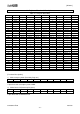
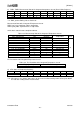
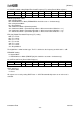
11). EHYS13, EHYS24: Hysteresis setting of Threshold Level / Polarity setting of INT output.
(Read / Write Registers)
Address
Name
D7
D6
D5
D4
D3
D2
D1
D0
19H
EHYS13
EHYS13_4
EHYS13_3
EHYS13_2
EHYS13_1
EHYS13_0
1AH
EHYS24
EHYS24_4
EHYS24_3
EHYS24_2
EHYS24_1
EHYS24_0
Reset
1
1
1
0
0
0
0
0
Hysteresis setting for Threshold levels
ETHYS13, EHYS24: Hysteresis setting for threshold levels 5-bit
This register is used only in Switch Mode (ECOPY).
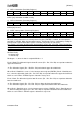
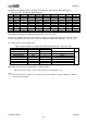
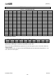
Table 14.6. Hysteresis setting of Threshold Level
Hysteresis [4:0]
Differential Current Output
Unit
Binary
Hex
Decimal
11111
1F
31
108.12
pA
11110
1E
30
104.63
⁞
⁞
⁞
⁞
00001
01
1
3.4877
00000
00
0
0
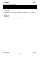
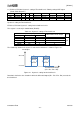
The relationship between the hysteresis and the threshold level is shown in Figure 14.1.
INT Output
“H” Level
“L” Level
EHYS13
or
EHYS24
EHYS13
or
EHYS24
The Differential Output
(IR1 - IR3 / IR2 - IR4)
Figure 14.1. Hysteresis setting for threshold levels.
Detection is defined as the situation in which the differential output (IR1 - IR3 / IR2 - IR4) exceeds the
threshold level.