
Data Sheet

[AK9753]
017005237-E-00 2017/04
- 32 -
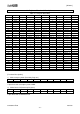
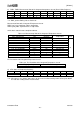
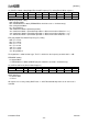
3). INFO1: Information (Read Only Registers)
Address
Name
D7
D6
D5
D4
D3
D2
D1
D0
02H
INFO1
0
0
0
0
0
0
0
1
INFO1 [7:0]: Information for AKM use only.
4). INFO2: Information (Read Only Registers)
Address
Name
D7
D6
D5
D4
D3
D2
D1
D0
03H
INFO2
0
0
0
0
0
0
0
0
INFO2 [7:0]: Reserve
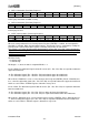
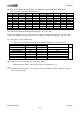
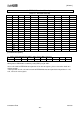
5). INTST: Interrupt Status (Read Only Registers)
Address
Name
D7
D6
D5
D4
D3
D2
D1
D0
04H
INTST
IR13H
IR13L
IR24H
IR24L
DR
Reset
1
1
1
0
0
0
0
0
When the correspondent bit in the Interrupt Source Register (EINTEN) is enabled, the interrupt to the
host MCU is available. When the interruption happens, the interrupt source is confirmed by reading the
interrupt status register. When INST register is read out, INT pin turns to “non-active”.
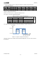
This register is rest, when the differential signal of two IR sensors (IR1 - IR3 / IR2 - IR4) are below “the
upper threshold levels - hysteresis” or the differential signal of two IR sensors (IR1 - IR3 / IR2 – IR4) are
above “the lower threshold levels + hysteresis” or the software reset is done or Write accessing to
ECNTL1 register is done.
DR: Data Ready
“0”: Normal state
“1”: Data Ready
DR bit goes “1”, when the data is ready with DRI bit = “1”
IR13H / IR24H: The differential signals of two IR sensors (IR1 - IR3 / IR2 - IR4) are equal to or above the
upper threshold levels.
“0”: The differential signals (IR1 – IR3/IR2 – IR4) are below the upper threshold levels.
“1”: The differential signals (IR1 – IR3/IR2 – IR4) are below the upper threshold levels.
When IR13H / IR24HI bit is set to “1” in the interrupt source registers(EINTEN), IR13H / IR24H bit turns
to “1”, when the differential signals (IR1 - IR3 / IR2 - IR4) are equal to or above the upper threshold levels
which are set in ETH13 / ETH24H registers. Otherwise it stays at “0”.
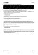
IR13L / IR24L: The differential signals of two IR sensors (IR1 - IR3 / IR2 - IR4) are equal to or below the
lower threshold levels.
“0”: The differential signals (IR1 - IR3 / IR2 - IR4) are above the lower threshold levels.
“1”: The differential signals (IR1 - IR3 / IR2 - IR4) are equal to or below the lower threshold levels.
When IR13LI / IR24LI bit set to “1” in the interrupt source registers (EINTEN), IR13L / IR24L bit turns to
“1”, when the differential signals (IR1 - IR3 / IR2 - IR4) are equal to or below the lower threshold levels
which are set in ETH13L / ETH24L registers. Otherwise it stays at “0”.