
Data Sheet

[AK9753]
017005237-E-00 2017/04
- 21 -
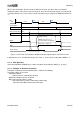
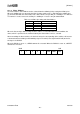
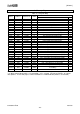
When a data read begins after the end of the Nth measurement, and when data read cannot be
completed until the end of the (N+1)th measurement, the measurement data registers are protected to
read data normally. In this case, because the(N+1)th data has been skipped, the DOR bit transitions to
“1”.
PD
Measurement
PD
Measurement
(N)
(N-1)
(N+1)
Internal Buffer
data(N-1)
data(N)
Measurement data register
data(N-1)
data(N)
data(N+2)
DRDY
Read-out data
ST1
data(N)
ST2
ST1
PD
Measurement
(N+2)
data(N+1)
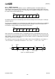
Data (N+1) is skipped.
DOR
Data register is protected
during read-out.
DRDY does not go to “1”
because data is not updated.
Figure 11.9. The data read cannot be completed until the beginning of the next measurement.
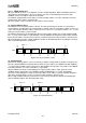
In both of these cases, the DOR bit changes to “0” from “1”, at the start of reading data if DRDY is “1”.
11.5.4. End Operation
Select Stand-by Mode (EMODE [2:0] = “000”) to complete the Continuous Mode 0 (1, 2, and 3).
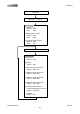
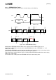
11.5.5. Example of Read-out Procedure
Example of read-out procedure of AK9753 data is shown in the following.
The below settings are assumed.
・Continuous Mode 0
--> Measurement is automatically repeated.
・Digital Filter Cutoff Frequency Fc=0.6Hz
・Data ready interrupt setting is enable.
--> INT output turns to “Active” at the timing of data ready.
After that, HOST MCU should read out the data.