
Data Sheet

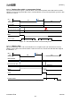

[AK9753]
017005237-E-00 2017/04
- 14 -
11.3 Operating Mode
11.3.1. Normal Mode/Switch Mode
AK9753 has two Modes, Normal Mode and Switch Mode.
Normal Mode is the mode which controls AK9753 by using I
2
C interface. The digital output the four IR
sensors and the internal temperature sensor can be used through the I
2
C interface in Normal Mode.
INT output also can be used.
Switch Mode is the mode which uses only INT output without using I
2
C interface. When the differential
output of two sensors (IR1 - IR3 / IR2 - IR4) exceeds the upper / lower thresholds which are set to
EEPROM, INT output turns “active”. When the differential output of two sensors (IR1 - IR3 / IR2 - IR4) is
in the range which is set to EEPROM, INT output is “non-active”. The hysteresis for the thresholds can
be set to EEPROM for avoiding the chattering of INT output. When Switch Mode is used, the threshold
and the hysteresis should be set to EEPROM beforehand. When the accuracy of HumanSensing is not
cared, Switch Mode can be used.
Normal Mode / Switch Mode selection is controlled by the CAD1 pin and CAD0 pin.
When CAD1 pin and CAD0 pin are set as CAD1 pin= CAD0 pin= “H”, the digital output can be used
through the I
2
C interface.
When CAD1 pin and CAD0 pin are set as CAD1 pin= CAD0 pin= “H”, Switch Mode is selected. When
Switch Mode is selected, SCL pin and SDA pin should be tied to “H”. (Do not access the AK9753 through
the I
2
C interface in Switch Mode.)
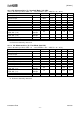
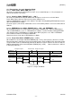
Table 11.2. CAD0 / CAD1 pin Setting and Slave Address
CAD1
CAD0
I
2
C output
Slave address
Mode
L
L
Enable
64H
Normal Mode
L
H
Enable
65H
Normal Mode
H
L
Enable
66H
Normal Mode
H
H
Disable
Prohibited
Switch Mode