
Data Sheet


2005-2013 Microchip Technology Inc. DS20001984F-page 15
MCP73831/2
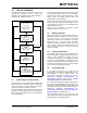
5.0 DETAILED DESCRIPTION
5.1 Analog Circuitry
5.1.1 BATTERY MANAGEMENT INPUT
SUPPLY (V
DD
)
The V
DD
pin is the input supply pin for the MCP73831/
2 devices. The MCP73831/2 automatically enter a
Power-Down mode if the voltage on the V
DD
input falls
below the UVLO voltage (V
STOP
). This feature prevents
draining the battery pack when the V
DD
supply is not
present.
5.1.2 CURRENT REGULATION SET
(PROG)
Fast charge current regulation can be scaled by placing
a programming resistor (R
PROG
) from the PROG input
to V
SS
. The program resistor and the charge current
are calculated using the following equation:
The preconditioning trickle charge current and the
charge termination current are ratiometric to the fast
charge current based on the selected device options.
5.1.3 BATTERY CHARGE CONTROL
OUTPUT (V
BAT
)
The battery charge control output is the drain terminal
of an internal P-channel MOSFET. The MCP73831/2
provide constant current and voltage regulation to the
battery pack by controlling this MOSFET in the linear
region. The battery charge control output should be
connected to the positive terminal of the battery pack.
5.2 Digital Circuitry
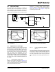
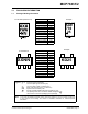
5.2.1 STATUS INDICATOR (STAT)
The charge status output of the MCP73831 has three
different states: High (H), Low (L), and High-
Impedance (Hi-Z). The charge status output of the
MCP73832 is open-drain. It has two different states:
Low (L) and High-Impedance (Hi-Z). The charge status
output can be used to illuminate one, two or tri-color
LEDs. Optionally, the charge status output can be used
as an interface to a host microcontroller.
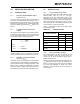
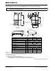
Table 5-1 summarizes the state of the status output
during a charge cycle.
5.2.2 DEVICE DISABLE (PROG)
The current regulation set input pin (PROG) can be
used to terminate a charge at any time during the
charge cycle, as well as to initiate a charge cycle or
initiate a recharge cycle.
Placing a programming resistor from the PROG input to
V
SS
enables the device. Allowing the PROG input to
float or by applying a logic-high input signal, disables
the device and terminates a charge cycle. When
disabled, the device’s supply current is reduced to
25 µA, typically.
I
REG
1000V
R
PROG
-----------------
=
Where:
R
PROG
=kOhms
I
REG
= milliampere
TABLE 5-1: STATUS OUTPUT
Charge Cycle State
STAT1
MCP73831 MCP73832
Shutdown Hi-Z Hi-Z
No Battery Present Hi-Z Hi-Z
Preconditioning L L
Constant-Current Fast
Charge
LL
Constant Voltage L L
Charge Complete –
Standby
HHi-Z