
Data Sheet

Page 91
RFM95/96/97/98(W)
Tel: + 86-755-82973805 Fax: +86- 755-82973550 E-mail: sales@hoperf.com http:/ / www.hoperf.com
WIRELESS & SENSING PRELIMINARY DATASHEET
Name
(Address)
Bits
Variable Name
Mode
Default
value
FSK/OOK Description
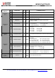
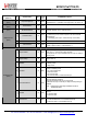
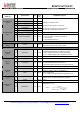
7-5 reserved rw 0x00 reserved
4-3 RxBwMantAfc rw 0x01 RxBwMant parameter used during the AFC
RegAfcBw
(0x13)
2-0 RxBwExpAfc rw 0x03 RxBwExp parameter used during the AFC
7-6 reserved rw 0x00 reserved
5
BitSyncOn
rw
0x01
Enables the Bit Synchronizer.
0 Æ Bit Sync disabled (not possible in Packet mode)
1 Æ Bit Sync enabled
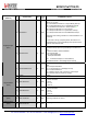
4-3
OokThreshType
rw
0x01
Selects the type of threshold in the OOK data slicer:
00 Æ fixed threshold 10 Æ average mode
01 Æ peak mode (default) 11 Æ reserved
RegOokPeak
(0x14)
2-0
OokPeakTheshStep
rw
0x00
Size of each decrement of the RSSI threshold in the OOK
demodulator:
000 Æ 0.5 dB 001 Æ 1.0 dB
010 Æ 1.5 dB 011 Æ 2.0 dB
100 Æ 3.0 dB 101 Æ 4.0 dB
110 Æ 5.0 dB 111 Æ 6.0 dB
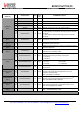
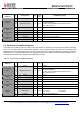
RegOokFix
(0x15)
7-0
OokFixedThreshold
rw
0x0C
Fixed threshold for the Data Slicer in OOK mode
Floor threshold for the Data Slicer in OOK when Peak mode is
used
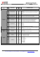
7-5
OokPeakThreshDec
rw
0x00
Period of decrement of the RSSI threshold in the OOK
demodulator:
000 Æ once per chip 001 Æ once every 2 chips
010 Æ once every 4 chips 011 Æ once every 8 chips
100 Æ twice in each chip 101 Æ 4 times in each chip
110 Æ 8 times in each chip 111 Æ 16 times in each chip
4 reserved rw 0x01 reserved
3-2
OokAverageOffset
rw
0x00
Static offset added to the threshold in average mode in order to
reduce glitching activity (OOK only):
00 Æ 0.0 dB 10 Æ 4.0 dB
01 Æ 2.0 dB 11 Æ 6.0 dB
RegOokAvg
(0x16)
1-0
OokAverageThreshFilt
rw
0x02
Filter coefficients in average mode of the OOK demodulator:
00 Æ f
C
≈ chip rate / 32.π 01 Æ f
C
≈ chip rate / 8.π
10 Æ f
C
≈ chip rate / 4.π 11 Æf
C
≈ chip rate / 2.π
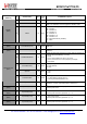
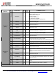
RegRes17
to
RegRes19
7-0
reserved
rw
0x47
0x32
0x3E
reserved. Keep the Reset values.