
Data Sheet

Page 82
RFM95/96/97/98(W)
Tel: + 86-755-82973805 Fax: +86- 755-82973550 E-mail: sales@hoperf.com http:/ / www.hoperf.com
WIRELESS & SENSING PRELIMINARY DATASHEET
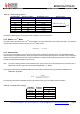
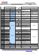
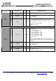
Table 83 RssiSmoothing Options
RssiSmoothing Number of Samples Estimated Accuracy Response Time
‘000’ 2 ± 6 dB
‘001’ 4 ± 5 dB
‘010’ 8 ± 4 dB
‘011’ 16 ± 3 dB
‘100’ 32 ± 2 dB
‘101’ 64 ± 1.5 dB
‘110’ 128 ± 1.2 dB
‘111’ 256 ± 1.1 dB
2
(
RssiSmoothing
+
1
)
4
·
RxBw
[
kHz
]
[
ms
]
The RSSI is calibrated when the image and RSSI calibration process is launched.
5.5.5. RSSI in
LoRa
TM
Mode
The RSSI values reported by the LoRa
TM
modem differ from those expressed by the FSK/OOK modem. The following
formula shows the method used to interpret the LoRa
TM
RSSI values.
R S S I
[
dB m ] = –137 + RSSI
5.5.6. Channel Filter
The role of the channel filter is to reject noise and interference outside of the wanted channel. The RFM95/96/97/98(W)
channel filtering is implemented with a 16-tap finite impulse response (FIR) filter. Rejection of the filter is high enough that
the filter stop-band performance is not the dominant influence on adjacent channel rejection performance. This is instead
limited by the RFM95/96/97/98(W) PLL phase noise.
Note To respect sampling criterion in the decimation chain of the receiver, the communication bit rate cannot be set at a
higher than twice the single side receiver bandwidth (BitRate < 2 x RxBw)
The programmed single side bandwidth RxBw of the channel filter is determined by the parameters RxBwMant and
RxBwExp in RegRxBw:
RxBw =
------------------------
F
----
X
----
O
----
S
----
C
-------------------------
RxB wMant
×
2
RxBwE
x
p + 2
The following channel filter bandwidths are hence accessible in the case of a 32 MHz reference oscillator.
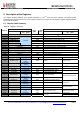
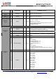
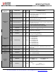
Table 84 Available RxBw Settings
RxBw (kHz) RxBwMant
(binary/value)
RxBwExp
(decimal)
FSK / OOK
10b / 24 7 2.6
01b / 20 7 3.1
00b / 16 7 3.9
10b / 24 6 5.2