
Data Sheet

Page 81
RFM95/96/97/98(W)
Tel: + 86-755-82973805 Fax: +86- 755-82973550 E-mail: sales@hoperf.com http:/ / www.hoperf.com
WIRELESS & SENSING PRELIMINARY DATASHEET
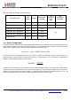
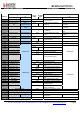
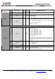
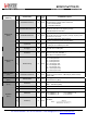
Table 82 LNA Gain Control and Performances
RX input level (Pin)
Gain
Setting
LnaGain
Relative LNA
Gain [dB]
NF
Lower/Higher
band
[dB]
IIP3
Lower/Higher
band [dBm]
Pin <= AgcThresh1
G1
‘001’
0 dB
5/7
-22/-12
AgcThresh1 < Pin <= AgcThresh2
G2
‘010’
-6 dB
9/11
-15/-8
AgcThresh2 < Pin <= AgcThresh3
G3
‘011’
-12 dB
AgcThresh3 < Pin <= AgcThresh4
G4
‘100’
-24 dB
AgcThresh4 < Pin <= AgcThresh5
G5
‘110’
-26 dB
AgcThresh5 < Pin
G6
‘111’
-48 dB
TBC
5.5.4. RSSI in FSK/OOK Mode
The RSSI provides a measure of the incoming signal power at RF input port, measured within the receiver bandwidth. The
signal power is available in RssiValue. This value is absolute in units of dBm and with a resolution of 0.5 dB. The formula
below relates the register value to the absolute input signal level at the RF input port:
RssiValue
= −
2
·
RF level
[
dBm
]
+
RssiOffset
[
dB
]
The RSSI value can be compensated to take into account the loss in the matching network or even the gain of an
additional LNA by using RssiOffset. The offset can be chosen in 1 dB steps from -16 to +15 dB. When compensation is
applied, the effective signal strength is read as follows:
RSSI
[
dBm
]
= −
RssiValue
2
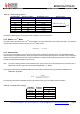
The RSSI value is smoothed on a user defined number of measured RSSI samples. The precision of the RSSI value is
related to the number of RSSI samples used. RssiSmoothing selects the number of RSSI samples from a minimum of 2
samples up to 256 samples in increments of power of 2. Table 83 gives the estimation of the RSSI accuracy for a 10 dB
SNR and response time versus the number of RSSI samples programmed in RssiSmoothing.