
Data Sheet

Page 78
RFM95/96/97/98(W)
Tel: + 86-755-82973805 Fax: + 86- 755-82973550 E-mail: sales@hoperf.com http:/ / www.hoperf.com
WIRELESS & SENSING PRELIMINARY DATASHEET
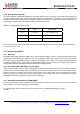
5.4. Transmitter Description
The transmitter of RFM95/96/97/98(W) comprises the frequency synthesizer, modulator (both LoRa
TM
and FSK/OOK) and
power amplifier blocks, together with the DC biasing and ramping functionality that is provided through the VR_PA block.
5.4.1. Architecture Description
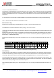
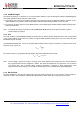
The architecture of the RF front end is shown in the following diagram.
Figure 40. RF Front-end Architecture Shows the Internal PA
Configuration.
5.4.2. RF Power Amplifiers
PA_HF and PA_LF are high efficiency amplifiers capable of yielding RF power programmable in 1 dB steps from -4 to
+14dBm directly into a 50 ohm load with low current consumption. PA_LF covers the lower bands (up to 525 MHz), whilst
PA_HF will cover the upper bands (from 860 MHz). The output power is sensitive to the power supply voltage, and typically
their performance is expressed at 3.3V.
PA_HP (High Power), connected to the PA_BOOST pin, covers all frequency bands that the chip addresses. It permits
continuous operation at up to +17 dBm and duty cycled operation at up to +20dBm. For full details of operation at +20dBm
please consult Section 5.4.3
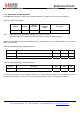
Table 77 Power Amplifier Mode Selection Truth Table
PaSelect
Mode
Power Range
Pout Formula
0
PA_HF or PA_LF on RFO_HF or RFO_LF -4 to +15dBm Pout=Pmax-(15-OutputPower)
Pmax=10.8+0.6*MaxPower [dBm]
1
PA_HP on PA_BOOST, any frequency +2 to +17dBm Pout=17-(15-OutputPower) [dBm]
Notes - For +20 dBm restrictions on operation please consult the following section.
- To ensure correct operation at the highest power levels ensure that the current limiter OcpTrim is adjusted to
permit delivery of the requisite supply current.
- If the PA_BOOST pin is not used it may be left floating.