
Data Sheet

Page 66
RFM95/96/97/98(W)
Tel: + 86-755-82973805 Fax: + 86- 755-82973550 E-mail: sales@hoperf.com http:/ / www.hoperf.com
WIRELESS & SENSING PRELIMINARY DATASHEET
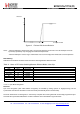
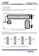
4.2.12.3. Rx Processing
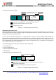
If the bit synchronizer is disabled, the raw demodulator output is made directly available on DATA pin and no DCLK signal
is provided.
Conversely, if the bit synchronizer is enabled, synchronous cleaned data and clock are made available respectively on
DIO2/DATA and DIO1/DCLK pins. DATA is sampled on the rising edge of DCLK and updated on the falling edge as
illustrated below.
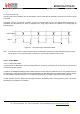
DATA (NRZ)
DCLK
Figure 31. Rx Processing in Continuous
Mode
Note In Continuous mode it is always recommended to enable the bit synchronizer to clean the DATA signal even if the
DCLK signal is not used by the uC (bit synchronizer is automatically enabled in Packet mode).
4.2.13. Packet Mode
4.2.13.1. General Description
In Packet mode the NRZ data to (from) the (de)modulator is not directly accessed by the uC but stored in the FIFO and
accessed via the SPI interface.
In addition, the RFM95/96/97/98(W) packet handler performs several packet oriented tasks such as Preamble and Sync
word generation, CRC calculation/check, whitening/dewhitening of data, Manchester encoding/decoding, address filtering,
etc. This simplifies software and reduces uC overhead by performing these repetitive tasks within the RF chip itself.
Another important feature is ability to fill and empty the FIFO in Sleep/Stdby mode, ensuring optimum power consumption
and adding more flexibility for the software.