
Data Sheet

Page 63
RFM95/96/97/98(W)
Tel: + 86-755-82973805 Fax: + 86- 755-82973550 E-mail: sales@hoperf.com http:/ / www.hoperf.com
WIRELESS & SENSING PRELIMINARY DATASHEET
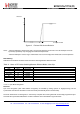
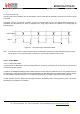
Rx DATA
(NRZ)
Bit N-x =
Sync_value[x]
Bit N-1 =
Sync_value[1]
Bit N =
Sync_value[0]
DCLK
SyncAddressMatch
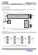
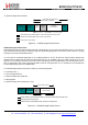
Figure 28. Sync Word
Recognition
During the comparison of the demodulated data, the first bit received is compared with bit 7 (MSB) of RegSyncValue1 and
the last bit received is compared with bit 0 (LSB) of the last byte whose address is determined by the length of the Sync
word.
When the programmed Sync word is detected the user can assume that this incoming packet is for the node and can be
processed accordingly.
SyncAddressMatch is cleared when leaving Rx or FIFO is emptied.
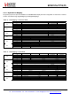
Configuration
Size: Sync word size can be set from 1 to 8 bytes (i.e. 8 to 64 bits) via SyncSize in RegSyncConfig. In Packet mode this
field is also used for Sync word generation in Tx mode.
Value: The Sync word value is configured in SyncValue(63:0). In Packet mode this field is also used for Sync word
generation in Tx mode.
Note SyncValue choices containing 0x00 bytes are not allowed
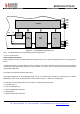
Packet Handler
The packet handler is the block used in Packet mode. Its functionality is fully described in section 4.2.13.
Control
The control block configures and controls the full chip's behavior according to the settings programmed in the configuration
registers.