
Data Sheet


Page 41
RFM95/96/97/98(W)
Tel: + 86-755-82973805 Fax: + 86- 755-82973550 E-mail: sales@hoperf.com http:/ / www.hoperf.com
WIRELESS & SENSING PRELIMINARY DATASHEET
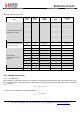
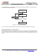
Table 63 DIO Mapping LoRa
TM
Mode
Operating
Mode
DIOx
Mapping
DIO5
DIO4
DIO3
DIO2
DIO1
DIO0
00
ModeReady CadDetected CadDone FhssChangeChannel RxTimeout RxDone
01
ClkOut PllLock ValidHeader FhssChangeChannel FhssChangeChannel TxDone
10
ClkOut PllLock PayloadCrcError FhssChangeChannel CadDetected CadDone
ALL
11
-
-
-
-
-
-
4.2. FSK/OOK Modem
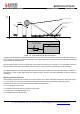
4.2.1. Bit Rate Setting
The bitrate setting is referenced to the crystal oscillator and provides a precise means of setting the bit rate (or equivalently
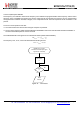
chip) rate of the radio. In continuous transmit mode (Section 3.2.2) the data stream to be transmitted can be input directly
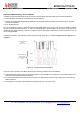
to the modulator via pin 9 (DIO2/DATA) in an asynchronous manner, unless Gaussian filtering is used, in which case the
DCLK signal on pin 10 (DIO1/DCLK) is used to synchronize the data stream. See section 4.2.2.3 for details on the
Gaussian filter.
In Packet mode or in Continuous mode with Gaussian filtering enabled, the Bit Rate (BR) is controlled by bits Bitrate in
RegBitrateMsb and RegBitrateLsb
Bi tR ate =
---------------------------
F
----
X
----
O
-----
S
---
C
------------------------------
Bi tR ate(15,0) +
-----
i
--
t
--
r
--
a
----
t
--
e
---
F
----
r
--
a
----
c
-
16
Note: BitrateFrac bits have no effect (i.e may be considered equal to 0) in OOK modulation mode.
The quantity BitrateFrac is hence designed to allow very high precision (max. 250 ppm programing resolution) for any
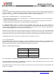
bitrate in the programmable range. Table 64 below shows a range of standard bitrates and the accuracy to within which
they may be reached.