
Data Sheet

Page 40
RFM95/96/97/98(W)
Tel: + 86-755-82973805 Fax: +86- 755-82973550 E-mail: sales@hoperf.com http:/ / www.hoperf.com
WIRELESS & SENSING PRELIMINARY DATASHEET
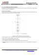
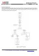
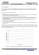
To illustrate this process and the respective consumption in each mode, the CAD process follows the sequence of events
outlined below:
Figure 12. Consumption Profile of the LoRa CAD Process
The receiver is then in full receiver mode for just over half of the activity detection, followed by a reduced consumption
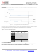
processing phase where the consumption varies with the LoRa bandwidth as shown in the table below.
Table 62 LoRa CAD Consumption Figures
Bandwidth
(kHz)
Full Rx, IDDR_L
(mA)
Processing, IDDC_L
(mA)
7.8
10.4
15.6
20.8
31.2
41.7
62.5
To be
confirmed
125 10.8 5.6
250 11.6 6.5
500 13 8
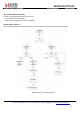
4.1.5.1. Digital IO Pin Mapping
Six of RFM95/96/97/98(W)’s general purpose IO pins are available used in LoRa
TM
mode. Their mapping is shown
below and depends upon the configuration of registers RegDioMapping1 and RegDioMapping2.