
Data Sheet

Page 25
RFM95/96/97/98(W)
Tel: + 86-755-82973805 Fax: +86- 755-82973550 E-mail: sales@hoperf.com http:/ / www.hoperf.com
WIRELESS & SENSING PRELIMINARY DATASHEET
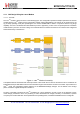
Forward error correction is particularly efficient in improving the reliability of the link in the presence of interference. So that
the coding rate (and so robustness to interference) can be changed in response to channel conditions - the coding rate can
optionally be included in the packet header for use by the receiver. Please consult Section 4.1.1.6 for more information on
the LoRa
TM
packet and header.
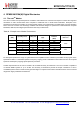
4.1.1.4. Signal Bandwidth
An increase in signal bandwidth permits the use of a higher effective data rate, thus reducing transmission time at the
expense of reduced sensitivity improvement. There are of course regulatory constraints in most countries on the
permissible occupied bandwidth. Contrary to the FSK modem which is described in terms of the single sideband
bandwidth, the LoRa
TM
modem bandwidth refers to the double sideband bandwidth (or total channel bandwidth). The range
of bandwidths relevant to most regulatory situations is given in the LoRa
TM
modem specifications table (see Section 2.4.5).
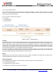
Bandwidth
(kHz)
Spreading Factor
Coding rate
Nominal Rb
(bps)
7.8 12 4/5 18
10.4 12 4/5 24
15.6 12 4/5 37
20.8 12 4/5 49
31.2 12 4/5 73
41.7 12 4/5 98
62.5 12 4/5 146
125 12 4/5 293
250 12 4/5 586
500 12 4/5 1172
Note In the lower band (169 MHz), the 250 kHz and 500 kHz bandwidths are not supported.
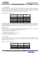
4.1.1.5.
LoRa
TM
Transmission Parameter Relationship
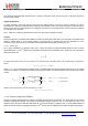
With a knowledge of the key parameters that can be controlled by the user we define the LoRa
TM
symbol rate as:
Rs =
-----
W
---
2
SF
where BW is the programmed bandwidth and SF is the spreading factor. The transmitted signal is a constant envelope
signal. Equivalently, one chip is sent per second per Hz of bandwidth.