
Data Sheet

Page 23
RFM95/96/97/98(W)
Tel: + 86-755-82973805 Fax: +86- 755-82973550 E-mail: sales@hoperf.com http:/ / www.hoperf.com
WIRELESS & SENSING PRELIMINARY DATASHEET
4.1.1. Link Design Using the LoRa
TM
Modem
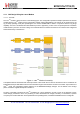
4.1.1.1. Overview
The LoRa
TM
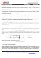
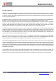
modem is setup as shown in the following figure. This configuration permits the simple replacement of the FSK
modem with the LoRa
TM
modem via the configuration register setting RegOpMode. This change can be performed on the
fly (in Sleep operating mode) thus permitting the use of both standard FSK or OOK in conjunction with the long range
capability. The LoRa
TM
modulation and demodulation process is proprietary, it uses a form of spread spectrum modulation
combined with cyclic error correction coding. The combined influence of these two factors is an increase in link budget and
enhanced immunity to interference.
Figure 4.
LoRa
TM
Modem Connectivity
A simplified outline of the transmit and receive processes is also shown above. Here we see that the LoRa
TM
modem has an
independent dual port data buffer FIFO that is accessed through an SPI interface common to all modes. Upon selection of
LoRa
TM
mode, the configuration register mapping of the RFM95/96/97/98(W) changes. For full details of this change
please consult the register description of Section 6.
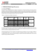
So that it is possible to optimise the LoRa
TM
modulation for a given application, access is given to the designer to three
critical design parameters. Each one permitting a trade off between link budget, immunity to interference, spectral
occupancy and nominal data rate. These parameters are spreading factor, modulation bandwidth and error coding rate.