
Data Sheet


Page 16
RFM95/96/97/98(W)
Tel: + 86-755-82973805 Fax: + 86- 755-82973550 E-mail: sales@hoperf.com http:/ / www.hoperf.com
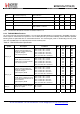
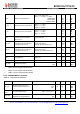
RF_OPH_
MAX
Max RF output power, on
PA_BOOST pin
High power mode -
+20
- dBm
ΔRF_
OPH_V
RF output power stability on PA_-
BOOST pin versus voltage supply.
VDD = 2.4 V to 3.7 V
-
+/-1
-
dB
ΔRF_T
RF output power stability versus
From T = -40 °C to +85 °C
-
+/-1
-
dB
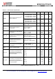
169 MHz band
10kHz Offset
50kHz Offset
400kHz Offset
1MHz Offset
-
-
-
-
-118
-118
-128
-132
-
-
-
-
dBc/
Hz
433 MHz band
10kHz Offset
50kHz Offset
400kHz Offset
1MHz Offset
-
-
-
-
-109
-109
-121
-128
-
-
-
-
dBc/
Hz
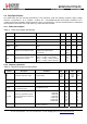
PHN
Transmitter Phase Noise
868/915 MHz band
10kHz Offset
50kHz Offset
400kHz Offset
1MHz Offset
-
-
-
-
-103
-103
-115
-122
-
-
-
-
dBc/
Hz
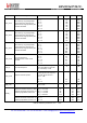
ACP
Transmitter adjacent channel
power (measured at 25 kHz offset)
BT=1. Measurement conditions as
defined by EN 300 220-1 V2.3.1
-
-
-37
dBm
TS_TR
Transmitter wake up time, to the
first rising edge of DCLK
Frequency Synthesizer enabled, PaR-
amp = 10us, BR = 4.8 kb/s
-
120
-
us
temperature on PA_BOOST pin.
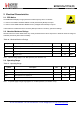
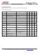
2.4.5. Electrical specification for Lora
TM
modulation
The table below gives the electrical specifications for the transceiver operating with Lora
TM
modulation. Following
conditions apply unless otherwise specified:
Supply voltage = 3.3 V.
Temperature = 25° C.
f
XOSC
= 32 MHz.
Lower bands: 169 MHz and 433 MHz, higher bands: 868 and 915 MHz
bandwidth (BW) = 125 kHz.
Spreading Factor (SF) = 12.
Error Correction Code (EC) = 4/6.
Packet Error Rate (PER)= 1%
CRC on payload enabled.
Output power = 13 dBm in transmission.
Payload length = 64 bytes.
Preamble Length = 12 symbols (programmed register PreambleLength=8)
With matched impedances