
Data Sheet


Page 13
RFM95/96/97/98(W)
Tel: + 86-755-82973805 Fax: + 86- 755-82973550 E-mail: sales@hoperf.com http:/ / www.hoperf.com
WIRELESS & SENSING PRELIMINARY DATASHEET
2.4. Chip Specification
The tables below give the electrical specifications of the transceiver under the following conditions: Supply voltage
VDD=3.3 V, temperature = 25 °C, FXOSC = 32 MHz, F
RF
= 169/434/868/915 MHz (see specific indication), Pout =
+13dBm, 2-level FSK modulation without pre-filtering, FDA = 5 kHz, Bit Rate = 4.8 kb/s and terminated in a matched 50
Ohm impedance, shared Rx and Tx path matching., unless otherwise specified.
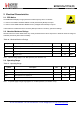
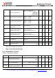
2.4.1. Power Consumption
Table 51 Power Consumption Specification
Symbol Description Conditions Min Typ Max Unit
IDDSL
Supply current in Sleep mode
- 0.2 1 uA
IDDIDLE Supply current in Idle mode RC oscillator enabled - 1.5 - uA
IDDST Supply current in Standby mode Crystal oscillator enabled - 1.6 1.8 mA
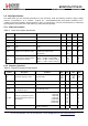
IDDFS
Supply current in Synthesizer
mode
FSRx
-
5.8
-
mA
IDDR
Supply current in Receive mode
LnaBoost Off, higher bands
LnaBoost On, higher bands
Lower bands
-
-
-
10.8
11.5
12.1
-
-
-
mA
IDDT
Supply current in Transmit mode
with impedance matching
RFOP = +20 dBm, on PA_BOOST
RFOP = +17 dBm, on PA_BOOST
RFOP = +13 dBm, on RFO_LF/HF pin
RFOP = + 7 dBm, on RFO_LF/HF pin
-
-
-
-
120
87
29
20
-
-
-
-
mA
mA
mA
mA
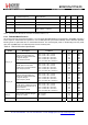
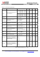
2.4.2. Frequency Synthesis
Table 52 Frequency Synthesizer Specification
Symbol
Description
Conditions
Min
Typ
Max
Unit
FR
Synthesizer frequency range
Programmable
137
410
862
-
-
-
175
525
1020
MHz
FXOSC
Crystal oscillator frequency
-
32
-
MHz
TS_OSC
Crystal oscillator wake-up time
-
250
-
us
TS_FS
Frequency synthesizer wake-up
time to PllLock signal
From Standby mode
-
60
-
us
TS_HOP
Frequency synthesizer hop time
at most 10 kHz away from the tar-
get frequency
200 kHz step
1 MHz step
5 MHz step
7 MHz step
12 MHz step
20 MHz step
25 MHz step
-
-
-
-
-
-
-
20
20
50
50
50
50
50
-
-
-
-
-
-
-
us
us
us
us
us
us
us
FSTEP Frequency synthesizer step
FSTEP = FXOSC/2
19
- 61.0 - Hz