
Data Sheet

Page 114
RFM95/96/97/98(W)
Tel: + 86-755-82973805 Fax: + 86- 755-82973550 E-mail: sales@hoperf.com http:/ / www.hoperf.com
WIRELESS & SENSING PRELIMINARY DATASHEET
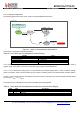
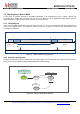
This example configuration is achieved as follows:
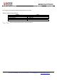
Table 92 Listen Mode with SyncAddress Condition Settings
Variable
Effect
IdleMode
1: Sleep mode
FromStart
00: To LowPowerSelection
LowPowerSelection
1: To Idle state
FromIdle
1: To Receive state on T1 interrupt
FromReceive
101: To Sequencer off on SyncAddress interrupt
FromRxTimeout
10: To LowPowerSelection
T
TimeoutRxPreamble
should be set to just long enough to catch a preamble (depends on PreambleDetectSize and BitRate).
T
Timer1
should be set to 64 µs (shortest possible duration).
T
Timer2
is set so that T
Timer1 +
T
Timer2
defines the time between two start of reception.
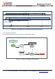
In order to insure packet detection and optimize the receiver power consumption, the received packet Preamble should be
defined so that T
Preamble =
T
Timer2
- T
SyncAddress
with T
SyncAddress
= (SyncSize + 1)*8/BitRate.
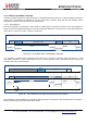
An example of DIO configuration for this mode is described in the following table:
Table 93 Listen Mode with PreambleDetect Condition Recommended DIO Mapping
DIO
Value
Description
0
01
CrcOk
1
00
FifoLevel
2
11
SyncAddress
3
00
FifoEmpty
4
11
PreambleDetect – Note: MapPreambleDetect bit should be set.