
Data Sheet

Page 111
RFM95/96/97/98(W)
Tel: + 86-755-82973805 Fax: + 86- 755-82973550 E-mail: sales@hoperf.com http:/ / www.hoperf.com
WIRELESS & SENSING PRELIMINARY DATASHEET
7.3.1.2. Sequencer Configuration
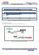
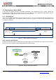
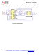
The following graph shows Listen mode - Wake on PreambleDetect state machine:
StateMachine
Sequencer
Off
&
Initial mode = Sleep or
Standby
Start bit
set
IdleMode = 1 :
Sleep
LowPower
LowPowerSelection =
1
Start
FromStart =
00
Selection
Idle
On
T1
FromIdle =
1
On
T2
Receive
On
PreambleDetect
FromReceive = 110
Sequencer
Off
Figure 47. Wake On PreambleDetect State
Machine
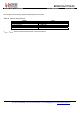
This example configuration is achieved as follows:
Table 90 Listen Mode with PreambleDetect Condition Settings
Variable
Effect
IdleMode
1: Sleep mode
FromStart
00: To LowPowerSelection
LowPowerSelection
1: To Idle state
FromIdle
1: To Receive state on T1 interrupt
FromReceive
110: To Sequencer Off on PreambleDetect interrupt
T
Timer2
defines the maximum duration the chip stays in Receive mode as long as no Preamble is detected. In order to
optimize power consumption, Timer2 must be set just long enough for Preamble detection.
T
Timer1
+ T
Timer2
defines the cycling period, i.e. time between two Preamble polling starts. In order to optimize average
power consumption, Timer1 should be relatively long. However, increasing Timer1 also extends packet reception duration.
In order to insure packet detection and optimize the receiver's power consumption, the received packet Preamble should
be as long as T
Timer1
+ 2 x T
Timer2
.
An example of DIO configuration for this mode is described in the following table:
Table 91 Listen Mode with PreambleDetect Condition Recommended DIO Mapping
DIO
Value
Description
0
01
CrcOk
1
00
FifoLevel
3
00
FifoEmpty
4
11
PreambleDetect – Note: MapPreambleDetect bit should be set.