
Data Sheet

Page 109
RFM95/96/97/98(W)
Tel: + 86-755-82973805 Fax: + 86- 755-82973550 E-mail: sales@hoperf.com http:/ / www.hoperf.com
WIRELESS & SENSING PRELIMINARY DATASHEET
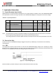
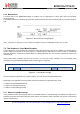
7.2.2. Manual Reset
A manual reset of the RFM95/96/97/98(W) is possible even for applications in which VDD cannot be physically
disconnected. Pin
7 should be pulled low for a hundred microseconds, and then released. The user should then wait for 5 ms before using the
chip.
Figure 43. Manual Reset Timing
Diagram
Note whilst pin 7 is driven low, an over current consumption of up to one milliampere can be seen on VDD.
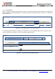
7.3. Top Sequencer: Listen Mode Examples
In this scenario, the circuit spends most of the time in Idle mode, during which only the RC oscillator is on. Periodically the
receiver wakes up and looks for incoming signal. If a wanted signal is detected, the receiver is kept on and data are
analyzed. Otherwise, if there was no wanted signal for a defined period of time, the receiver is switched off until the next
receive period.
During Listen mode, the Radio stays most of the time in a Low Power mode, resulting in very low average power
consumption. The general timing diagram of this scenario is given in Figure 44.
Listen
m
ode:
prin
ciple
Receive
Idle ( Sleep + RC )
Receive
Idle
Figure 44. Listen Mode:
Principle
An interrupt request is generated on a packet reception. The user can then take appropriate action.
Depending on the application and environment, there are several ways to implement Listen mode:
Wake on a PreambleDetect interrupt
Wake on a SyncAddress interrupt
Wake on a PayloadReady interrupt
7.3.1. Wake on Preamble Interrupt
In one possible scenario, the sequencer polls for a Preamble detection. If a preamble signal is detected, the sequencer is
switched off and the circuit stays in Receive mode until the user switches modes. Otherwise, the receiver is switched off
until the next Rx period.