
Data Sheet

Page 107
RFM95/96/97/98(W)
Tel: + 86-755-82973805 Fax: + 86- 755-82973550 E-mail: sales@hoperf.com http:/ / www.hoperf.com
WIRELESS & SENSING PRELIMINARY DATASHEET
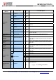
Name
(Address)
Bits
Variable Name
Mode
Reset
LoRa
TM
Description
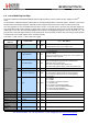
7-4
SpreadingFactor
rw
0x07
SF rate (expressed as a base-2 logarithm)
6 Æ 64 chips / symbol
7 Æ 128 chips / symbol
8 Æ 256 chips / symbol
9 Æ 512 chips / symbol
10 Æ 1024 chips / symbol
11 Æ 2048 chips / symbol
12 Æ 4096 chips / symbol
other values reserved.
3
TxContinuousMode
rw
0
0 Æ normal mode, a single packet is sent
1 Æ continuous mode, send multiple packets across the FIFO
(used for spectral analysis)
2
RxPayloadCrcOn
rw
0x00
CRC Information extracted from the received packet header
0 Æ Header indicates CRC off
1 Æ Header indicates CRC on
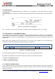
RegModemConfig
2
(0x1E)
1-0 SymbTimeout(9:8) rw 0x00 RX Time-Out MSB
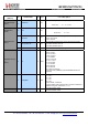
RegSymbTimeoutL
sb
(0x1F)
7-0
SymbTimeout(7:0)
rw
0x64
RX Time-Out LSB
RX operation time-out value expressed as number of symbols:
TimeOut = SymbT imeout
·
Ts
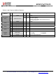
RegPreambleMsb
(0x20)
7-0
PreambleLength(15:8)
rw
0x0
Preamble length MSB, = PreambleLength + 4.25 Symbols
See Section XX for more details.
RegPreambleLsb
(0x21)
7-0
PreambleLength(7:0)
rw
0x8
Preamble Length LSB
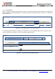
RegPayloadLength
(0x22)
7-0
PayloadLength(7:0)
rw
0x1
Payload length in bytes. The register needs to be set in implicit
header mode for the expected packet length. A 0 value is not
permitted
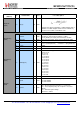
RegMaxPayloadLe
ngth
(0x23)
7-0
PayloadMaxLength(7:0)
rw
0xff
Maximum payload length; if header payload length exceeds
value a header CRC error is generated. Allows filtering of packet
with a bad size.
RegHopPeriod
(0x24)
7-0
FreqHoppingPeriod(7:0)
rw
0x0
Symbol periods between frequency hops. (0 = disabled). 1st hop
always happen after the 1st header symbol
RegFifoRxByteAdd
r
(0x25)
7-0
FifoRxByteAddrPtr
r
n/a
Current value of RX databuffer pointer (address of last byte
written by Lora receiver)
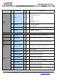
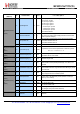
7-4 Unused r 0x00
3
MobileNode rw 0x00 0 Æ Use for static node
1 Æ Use for mobile node
2
AgcAutoOn rw 0x00 0 Æ LNA gain set by register LnaGain
1 Æ LNA gain set by the internal AGC loop
RegModemConfig
3
(0x26)
1-0 Reserved rw 0x00 Reserved
(0x27) - (0x3F)
-
Reserved
r
n/a
Reserved