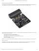
/22/2018 micro:bot Kit Experiment Guide - learn.sparkfun.com About the moto:bit Board The moto:bit is a carrier board for the micro:bit. Similar to an Arudino shield, it is designed to add functionality to the micro:bit without the hassle of a number of other boards, soldering, and all of those jumper wires. In this case, the moto:bit takes a micro:bit and turns it into a full blown robotics platform.
1/22/2018 micro:bot Kit Experiment Guide - learn.sparkfun.com H-Bridge and Motor Pins An H-Bridge is a chip that is the heart of a robot when it comes to driving motors and more specifically driving motors in both directions. Depending on the electrical state of specific pins on the H-Bridge, a motor drives forwards, backwards, and at different speeds. The good thing about this board is that if you are using Microsoft MakeCode, you actually don’t really need to know a whole lot about the H-Bridge itself.
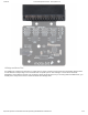
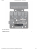
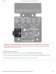
1/22/2018 micro:bot Kit Experiment Guide - learn.sparkfun.com To connect the hobby motors that are included in the kit, you can insert them into the 2-pin female connectors just above the motor pins. The connectors are highlighted in the image below. Keep in mind that direction the hobby motors will move depends on the code to control the H-bridge motor driver, how the motors are attached to a chassis, and the way the motors are wired to the input pins. https://learn.sparkfun.
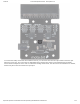
1/22/2018 micro:bot Kit Experiment Guide - learn.sparkfun.com Motor Control Switch The moto:bit has a switch that controls the power supply to the motors. That way you can have the robot powered while working on it or programming it and know that the robot is not going to start moving and drive off of the table. Believe us… that happens all the time! https://learn.sparkfun.
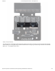
1/22/2018 micro:bot Kit Experiment Guide - learn.sparkfun.com Input and Output Pins The male pins on the moto:bit are for hooking up various inputs and outputs on your robot without using a breadboard to build elaborate circuits. https://learn.sparkfun.
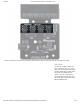
1/22/2018 micro:bot Kit Experiment Guide - learn.sparkfun.com We have a number of sensors and actuators that are built in this pin formation and will work with this board. Servo Ports No robot is complete without an arm, a swiveling “head,” or some other type of movement other than wheels. Notice that a couple of the pin groups are designated as “Servo”. You can connect servo motors directly to these pins and use them right out of the box with Microsoft MakeCode. https://learn.sparkfun.
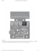
1/22/2018 micro:bot Kit Experiment Guide - learn.sparkfun.com I2C Port We broke out the I2C port of the micro:bit to an external port so that you can add any I2C capable sensor or actuator you can think of. It is standard pin arrangement to many of our I2C sensor breakout boards. https://learn.sparkfun.
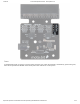
1/22/2018 micro:bot Kit Experiment Guide - learn.sparkfun.com Power A standard barrel jack connector is used for easily powering your robot. We find that a 4xAA battery pack works great, but it will accept between 2V-11V at the barrel jack. That’s a whole lot of robo-power! https://learn.sparkfun.
1/22/2018 micro:bot Kit Experiment Guide - learn.sparkfun.com Maximum Input Voltage Range for Vcc: The silkscreen indicates that the maximum input voltage range is between 3V to 17V. However, the actual voltage range that the board can support through the barrel jack is between 2V to 11V. Please do not apply more than 11V to the power jack on the moto:bit. We are currently updating our boards to resolve this issue. Assembling Your Robot This section will cover how to assemble your robot chassis.
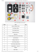
1/22/2018 micro:bot Kit Experiment Guide - learn.sparkfun.com Click on the image for a closer look. Letter Part Qty A Bottom Chassis Plate 1 B Top Chassis Plate 1 C Front Motor Mount 2 D Rear Motor Mount 2 E Side Strut 4 F Encoder Mount (Not Used in this Guide) 2 G moto:bit Mount 2 H Battery Pack Clip 1 I Line Follower Mount 1 J Line Follower Mount Plate 1 K Jumper Wire — 3-pin, 6" 3 L Wheels 2 M Nub Caster 1 https://learn.sparkfun.
1/22/2018 micro:bot Kit Experiment Guide - learn.sparkfun.com N DC Motors 2 O Line Follower Boards 3 P 4xAA Battery Holder 1 Q 4xAA Batteries (Not Included) 3 micro:bit Not Included in Kit 1 moto:bit Included in Kit 1 No Tools Necessary The robot chassis does not require any additional tools. WARNING: Do not attempt to remove chassis parts by squeezing them with pliers. If you try to muscle it too much you risk breaking them and compromising the structure of your robot. Handle with care.
1/22/2018 micro:bot Kit Experiment Guide - learn.sparkfun.com Notice that we consider the SparkFun moto:bit to be on the “back” of the bot and the Bumper Whiskers and Line Follower Boards to be in the “front.” Assembly Installing Motors Let’s begin by installing the motors that will control the wheels. Locate the following: https://learn.sparkfun.
1/22/2018 micro:bot Kit Experiment Guide - learn.sparkfun.com Attach Rear Motor Mounts Hold the wires near the middle of the Motor (N), and carefully slide a Rear Motor Mount (D) in from the side and over the two motor wires. Be careful not to snag the wires, the cable tie, or the clear plastic strap. Holding the motor wires, gently twist the Rear Motor Mount counter clockwise so that it snaps in place on the motor and the wires are centered in the gap of the motor mount.
1/22/2018 micro:bot Kit Experiment Guide - learn.sparkfun.com Attach the Front Motor Mounts Slide a Front Motor Mount (C) onto the protruding eyelet on the front of a Motor (N). Ensure the rounded sides of the motor mounts are facing the same way. Repeat the process for the second motor. https://learn.sparkfun.
1/22/2018 micro:bot Kit Experiment Guide - learn.sparkfun.com Attach the Motor Assemblies to the Chassis Snap one of the motor assemblies into the left two horizontal slots of the Bottom Chassis Plate (A). Make sure that the rounded edges of the motor mounts and the wires are facing toward the center of the chassis. Repeat for the opposite motor. Attach the Wheels Slide one Wheel (L) onto the plastic shaft of a Motor (N). Look at the motor shaft. Notice it has two flat edges.
1/22/2018 micro:bot Kit Experiment Guide - learn.sparkfun.com Repeat with the other wheel. Installing the Line Sensors This section will cover the Line Following Sensors array assembly. You’ll first build the Line Following array and then attach it to the chassis. Locate the following: https://learn.sparkfun.
1/22/2018 micro:bot Kit Experiment Guide - learn.sparkfun.com Construct the Line Follower Assembly Attach the three Line Follower Boards (O) to the Line Follower Mount (I) such that the rectangular pegs in the Line Follower Mount poke through the mounting holes in the Line Follower Boards. Make sure the sensors are facing away/down from the clip of the mount.
1/22/2018 micro:bot Kit Experiment Guide - learn.sparkfun.com Attach the Cables You will need to connect a 3-Wire Jumper Cable (K) to each of the Line Follower Boards (O). Note the color of the wire attached to each pin. Line Follower Connections: Jumper Wire Color RedBot Sensor - Line Follower Red GND Orange VCC Yellow OUT Attach all 3 cables to the 3 Line Follower Boards. Notice that the yellow wire should be on the right (out) and the red wire should be on the left (ground). https://learn.
1/22/2018 micro:bot Kit Experiment Guide - learn.sparkfun.com Attach the Line Follower Assembly to the Chassis Locate the wide, rectangular slot near the front of the chassis and snap the line follower assembly in from the bottom side of the chassis. Route the cables through the large hole in the bottom plate. The bottom of your chassis should look like the following image allowing the line sensors to be facing down. https://learn.sparkfun.
1/22/2018 micro:bot Kit Experiment Guide - learn.sparkfun.com Final Assembly With the motors and a few sensors attached, we can assemble the main body of the robot. Locate the following: You will also need the Top Chassis Plate and Bottom Chassis Plate assemblies, which have any additional parts and sensors you attached in previous steps. Attach the Nub Caster https://learn.sparkfun.
1/22/2018 micro:bot Kit Experiment Guide - learn.sparkfun.com Snap the Nub Caster (M) into the slot on the back of the Bottom Chassis Plate assembly. Make sure the Nub Caster is on the side opposite the motors (the bottom side). Add the Side Struts Snap the four Side Struts (E) into the diagonal slots on the four corners of the Bottom Chassis Plate assembly. Pull the cables through the cutouts on the chassis. https://learn.sparkfun.
1/22/2018 micro:bot Kit Experiment Guide - learn.sparkfun.com Route the Cables Position the Top Chassis Plate over the Bottom Chassis Plate – but do not snap the two plates together yet. Make sure that the front sides of each plate line up. Route the wires and cables through the left and right oval slots in the Top Chassis Plate assembly as shown. For the center line follower sensor, route this cable through the right oval slot. Note that SIK-only cables are listed with an asterisk (*).
1/22/2018 micro:bot Kit Experiment Guide - learn.sparkfun.com Attach Top Chassis Plate Assembly Line up the Top Chassis Plate on top of all the struts, and carefully snap the Top Chassis Plate assembly onto the side struts and motor mounts. Press gently above each side strut individually until they each snap into place. If you have the Bumpers installed, make sure the boards are between the top and bottom plates.
1/22/2018 micro:bot Kit Experiment Guide - learn.sparkfun.com In this section, you will add brains of the robot: the SparkFun moto:bit. Locate the following: You will also need the full chassis assembly, which contains any additional parts and sensors you attached in previous steps. Attach the moto:bit Mounts Snap the two moto:bit mounts (G) into the vertical slots in the back of the top chassis plate near the large rectangular opening.
1/22/2018 micro:bot Kit Experiment Guide - learn.sparkfun.com Add the moto:bit Before you snap in the moto:bit board, insert your micro:bit into the moto:bit as shown here. The moto:bit snaps into the lowest of the notches on the moto:bit Mounts (G). Make sure the power jack is facing the left side of the robot. Push gently and evenly until it snaps into place. https://learn.sparkfun.
1/22/2018 micro:bot Kit Experiment Guide - learn.sparkfun.com NOTE:The other slots in the moto:bit mounts can be used to hold the Arduino UNO or the Sparkfun RedBoard. Connecting the Cables It is time to connect the jumper wires; it is really important that these connections are right. You can follow along with the pin out tables or scroll down for a diagram. Trace each cable poking through the top chassis plate to make sure you know what it is connected to. https://learn.sparkfun.
1/22/2018 micro:bot Kit Experiment Guide - learn.sparkfun.com Please Note: When you have the micro:bot upright and the front of the chassis facing away from you, "left" sensors/motors will be on the left side and "right" sensors/motors will be on the right side. Also, the motor wires are intentionally switched for the right motor -- see notes below. Line Followers Left Line Follower: SparkFun moto:bit Pins Jumper Wires Left Line Follower Board P0 3-Wire Jumper Cable Yellow OUT 3.
1/22/2018 micro:bot Kit Experiment Guide - learn.sparkfun.com P1 3-Wire Jumper Cable Yellow OUT 3.3V 3-Wire Jumper Cable Orange VCC GND 3-Wire Jumper Cable Red GND SparkFun moto:bit Pins Jumper Wires Right Line Follower Board P2 3-Wire Jumper Cable Yellow OUT 3.3V 3-Wire Jumper Cable Orange VCC GND 3-Wire Jumper Cable Red GND Right Line Follower: Motors https://learn.sparkfun.
1/22/2018 micro:bot Kit Experiment Guide - learn.sparkfun.com Left Motor: SparkFun moto:bit Pins Left Motor Jumper Wires LEFT MOTOR - RED Soldered on Motor Jumper Wire - RED LEFT MOTOR - BLACK Soldered on Motor Jumper Wire - BLACK Right Motor: moto:bit Pins Right Motor Jumper Wires RIGHT MOTOR - RED Soldered on Motor Jumper Wire - BLACK RIGHT MOTOR - BLACK Soldered on Motor Jumper Wire - RED https://learn.sparkfun.
1/22/2018 micro:bot Kit Experiment Guide - learn.sparkfun.com Once all wires are connected it should look like the following image. Batteries The last step is to provide a power source for the micro:bot. You will need to provide your own AA batteries (Q). Locate the following: https://learn.sparkfun.
1/22/2018 micro:bot Kit Experiment Guide - learn.sparkfun.com Insert Batteries Insert the AA batteries into the Battery Holder (P). Makes sure the batteries are facing the correct direction, as per the markings inside of the Battery Holder. Attach Battery Pack Insert the Battery Holder (P) with batteries into the back cavity of the chassis. Position the Battery Holder so that the barrel jack cable comes out on the left side of the robot. https://learn.sparkfun.
1/22/2018 micro:bot Kit Experiment Guide - learn.sparkfun.com Insert the Battery Pack Clip (H) on top of the battery pack. Twist and position the clip so that it rests on top of the battery pack. https://learn.sparkfun.
1/22/2018 micro:bot Kit Experiment Guide - learn.sparkfun.com Push the clip down into the vertical slots in the Bottom Chassis Plate so it snaps in place. Route the barrel jack cable out of the left side of the chassis and up to the moto:bit. https://learn.sparkfun.
1/22/2018 micro:bot Kit Experiment Guide - learn.sparkfun.com Plug the barrel jack cable into the barrel connector on the side of the moto:bit carrier board. Changing the Batteries If you find that you need to replace the batteries in the micro:bot, the process is simple. Unplug the battery pack from the moto:bit. https://learn.sparkfun.
1/22/2018 micro:bot Kit Experiment Guide - learn.sparkfun.com Turn the micro:bot over and push on the Battery Holder through the hole in the Bottom Chassis Plate. This will cause the Battery Pack Clip to unsnap from the Bottom Chassis Plate. https://learn.sparkfun.
1/22/2018 micro:bot Kit Experiment Guide - learn.sparkfun.com Slide the Battery Pack and Clip out from the back of the micro:bot. https://learn.sparkfun.
1/22/2018 micro:bot Kit Experiment Guide - learn.sparkfun.com Change the batteries, and follow the steps in Attach Battery Pack section above to put the Battery Pack back in the micro:bot. Installing the moto:bit Package in MakeCode To make the most out of the moto:bit with the least amount of coding, use the Microsoft MakeCode package we wrote for the moto:bit board. Packages https://learn.sparkfun.
1/22/2018 micro:bot Kit Experiment Guide - learn.sparkfun.com If you have used Arduino before, you probably know about a thing called a library; which is a collection of code that extends the functionality of the core programming language. MakeCode packages work the same way. There are some amazing differences between Arduino libraries and MakeCode packages.
1/22/2018 micro:bot Kit Experiment Guide - learn.sparkfun.com Great! You have now installed the moto:bit package and are ready to use the board as well as the components that come in the micro:bot kit. As a side note, for every new MakeCode project that you make, you will have to load packages over again.
1/22/2018 micro:bot Kit Experiment Guide - learn.sparkfun.com https://learn.sparkfun.
1/22/2018 micro:bot Kit Experiment Guide - learn.sparkfun.com Motors take electrical energy and turn it into mechanical energy through putting a current through a coil of wire that creates a magnetic field. This then interacts with magnets in the motor, causing a push / pull effect. If you do that in a proper spacing and timing then you can spin a shaft. These motors operate in a similar was as mentioned above, but they have a bit of help; a gear box.
1/22/2018 micro:bot Kit Experiment Guide - learn.sparkfun.com First of all make sure that your red and black wires are plugged into your moto:bit and that they are in the correct ports. If you look closely the right and left ports are opposite from one another. Why is that? Well, in robotics the right and left motors are mirrors of one another, which means they go in opposite directions from one another to go forward, hence the ports being backwards.
1/22/2018 micro:bot Kit Experiment Guide - learn.sparkfun.com We are going to use Microsoft MakeCode to program the micro:bit. Please open a browser window and navigate to makecode.microbit.org. This should open the MakeCode environment that you used to install the moto:bit package in. Did you install the moto:bit package? To add the moto:bit package as instructed in the Installing the moto:bit Package in MakeCode section of this tutorial.
1/22/2018 micro:bot Kit Experiment Guide - learn.sparkfun.com Code to Note On Button Pressed The On Button Press is an event function. Any code blocks that are placed inside of the block will only execute when that event happens. In this block when the A button is pressed on your micro:bit your robot will start moving. When it gets to the end of the program it will stop again until you press the A button again.
1/22/2018 micro:bot Kit Experiment Guide - learn.sparkfun.com The pause block is like a code stop sign. It tells the micro:bit to wait for a given amount of time in milliseconds. While it is waiting whatever you told before the pause will keep happening. So, if you want your robot to drive forward for 2 seconds, you set the robots motors to drive forward and then pause for 2000 milliseconds and then have the motors do something else, like stop.
1/22/2018 micro:bot Kit Experiment Guide - learn.sparkfun.com Troubleshooting Robot not moving - Make sure your motors are hooked up correctly in the motor ports and your motor power switch is set to “run”, the battery pack is plugged in and you have fresh batteries Moving in reverse?! - You can flip the wiring of your motor or use the Set Motor Invert block in your On Start block to change what is forward vs. reverse.
1/22/2018 micro:bot Kit Experiment Guide - learn.sparkfun.com https://learn.sparkfun.
1/22/2018 micro:bot Kit Experiment Guide - learn.sparkfun.com The Line Follower sensor is an add-on for your shadow chassis that gives your robot the ability to detect lines or nearby objects. The sensor works by detecting reflected light coming from its own infrared LED. By measuring the amount of reflected infrared light, it can detect transitions from light to dark (lines) or even objects directly in front of it.
1/22/2018 micro:bot Kit Experiment Guide - learn.sparkfun.com The line sensors hookup to your moto:bit via female / female jumper wires that snake through the chassis of your robot up to the moto:bit. The sensors hookup to the moto:bit in the following order: LEFT => P0 CENTER => P1 RIGHT => P2 Double check to make sure they are hooked up correctly and in the proper orientation Running Your Script https://learn.sparkfun.
1/22/2018 micro:bot Kit Experiment Guide - learn.sparkfun.com Be sure to add the moto:bit package as instructed in the Installing the moto:bit Package in MakeCode section of this tutorial. Now, you can either download the following example script below and drag and drop it onto your micro:bit, or use it as an example and build it from scratch in MakeCode. Calibration is very important with the line sensors to work accurately.
1/22/2018 micro:bot Kit Experiment Guide - learn.sparkfun.com Creating a Variable In Microsoft MakeCode you need to be able to create variables to store information for your robot to compare against, or to just remember. You can use the built in variables under the Variables drawer as shown below. https://learn.sparkfun.
1/22/2018 micro:bot Kit Experiment Guide - learn.sparkfun.com But, you can also make your own custom variables. To do this click on the Variables drawer and select Make New Variable. You can then name it and use it in your program. Set To To store a value or piece of information in a variable you use the Set to block. This allows you to select a variable and set it to a value block of your choice. In this case the line sensor value on pin A0.
1/22/2018 micro:bot Kit Experiment Guide - learn.sparkfun.com To compare the current reading of the line sensor to its known baseline value that was captured and stored in the On Start block we use an if statement block. The if block accepts a logical statement. If that statement (Sensor Value < Surface - 30) is true then the if block runs then “then” section of code. If that statement is false then the “else” section of the block is run. You may be asking yourself why subtract 30 from the surface value.
1/22/2018 micro:bot Kit Experiment Guide - learn.sparkfun.com Your robot will drive forward until the black tape is directly under the center line sensors. When that happens your robot will stop, reverse, pivot a bit and try to drive forward again, hitting a line once more.
1/22/2018 micro:bot Kit Experiment Guide - learn.sparkfun.com Robot doesn’t detect line - If changing the width of your line doesn’t help, remember line sensor calibration settings can be very sensitive depending on your environment. Experiment 3: Following a Line Introduction OK, you have your robot staying inside of box drawn on the floor, but that still seems a little odd and random.
1/22/2018 micro:bot Kit Experiment Guide - learn.sparkfun.com https://learn.sparkfun.
1/22/2018 micro:bot Kit Experiment Guide - learn.sparkfun.com In the previous experiment you used a single line sensor (the middle sensor) to detect the line on the floor. That is great for staying inside of a line, but now, you need to follow a line. That is where the other two line sensors come in. Essentially, you want the center sensor to detect the line, but not the other two, meaning that the robot is centered on the line.
1/22/2018 micro:bot Kit Experiment Guide - learn.sparkfun.com The line sensors hookup to your moto:bit via female / female jumper wires that snake through the chassis of your robot up to the moto:bit. The sensors hookup to the moto:bit in the following order: LEFT => PO CENTER => P1 RIGHT => P2 Double check to make sure they are hooked up correctly and in the proper orientation Running Your Script https://learn.sparkfun.
1/22/2018 micro:bot Kit Experiment Guide - learn.sparkfun.com Be sure to add the moto:bit package as instructed in the Installing the moto:bit Package in MakeCode section of this tutorial. Now, you can either download the following example script below and drag and drop it onto your micro:bit, or use it as an example and build it from scratch in MakeCode. Calibration is very important with the line sensors to work accurately.
1/22/2018 micro:bot Kit Experiment Guide - learn.sparkfun.com lCal / rCal Like in the previous experiment, you need to set a baseline value for the surface that your robot is driving on. This is actually called a calibration value. Like the previous experiment, we need to do this, but for two sensors; right and left. We go through the same routine we did for the single sensor previously, but for the right and left sensors.
1/22/2018 micro:bot Kit Experiment Guide - learn.sparkfun.com https://learn.sparkfun.
1/22/2018 micro:bot Kit Experiment Guide - learn.sparkfun.com Your robot should drive forward until one of the side line sensors detects the line and then it will turn in that direction to correct itself. Depending on your line shape and thickness your robot may “waddle” more or less. Go Further: Your robot can go where you tell it by following a line.
1/22/2018 micro:bot Kit Experiment Guide - learn.sparkfun.com Robot doesn’t detect line - If changing the width of your line doesn’t help, remember line sensor calibration settings can be very sensitive depending on your environment. Experiment 4: Using the Accelerometer Introduction Now, what happens when something bumps into your robot? It just stays there and take it from this bully? No! It should move out of the way, or do something.
1/22/2018 micro:bot Kit Experiment Guide - learn.sparkfun.com https://learn.sparkfun.
1/22/2018 micro:bot Kit Experiment Guide - learn.sparkfun.com Like the magnetometer (compass), the accelerometer is on the micro:bit itself. Accelerometers are devices that measure acceleration, which is the rate of change of the velocity of an object. They measure in meters per second squared (m/s2) or in G-forces (g). A single G-force for us here on planet Earth is equivalent to 9.
1/22/2018 micro:bot Kit Experiment Guide - learn.sparkfun.com Code to Note On [Accelerometer] The micro:bit has a built in accelerometer that measures the gravitational forces that are acting upon it. With other microcontrollers this is sometimes hard to use and make sense of the data you receive from the sensor.
1/22/2018 micro:bot Kit Experiment Guide - learn.sparkfun.com If you tap the robot hard enough it will run / drive away from you. If you flip it over the motors will turn off. Same thing holds true if you place it on its tail with the micro:bit pointing up. Try playing around with the different events that you can trigger with the accelerometer.
1/22/2018 micro:bot Kit Experiment Guide - learn.sparkfun.com Craft Supplies 2x Skewers Hot Glue and Gun Optional: Electrical Tape Introduction to the Servo Motor https://learn.sparkfun.
1/22/2018 micro:bot Kit Experiment Guide - learn.sparkfun.com Unlike the action of most motors that continuously rotate, a servo motor can rotate to and hold a specific angle until it is told to rotate to a different angle. You can control the angle of the servo by sending it a Pulse Width Modulation (PWM) pulse train (turning a pin on and off really fast at different intervals); the PWM signal is mapped to a specific angle from 0 to 180 degrees in the servo block in MakeCode.
1/22/2018 micro:bot Kit Experiment Guide - learn.sparkfun.com different colors; red, black and white. Red is the supply voltage, black is ground and white is the signal. Hook the two servos up to the moto:bit at the two labeled servo ports. Make sure you line up ground to ground. The “right” servo is connected to pin P16 while the “left” is connected to pin P15. Using a bit of hot glue or tape, you can attach the servos to each side of the robot chassis.
1/22/2018 micro:bot Kit Experiment Guide - learn.sparkfun.com Don’t have any skewers laying around? Be creative here! Bot Assembled with Servos This Battle Bot utilized electrical tape to mount the jousting lances to the servo motors, and it ended up looking something like this… https://learn.sparkfun.
1/22/2018 micro:bot Kit Experiment Guide - learn.sparkfun.com Now, set your contraption aside until you have uploaded your code. Running Your Script Be sure to add the moto:bit package as instructed in the Installing the moto:bit Package in MakeCode section of this tutorial. Now, you can either download the following example script below and drag and drop it onto your micro:bit, or use it as an example and build it from scratch in MakeCode. Code to Note https://learn.sparkfun.
1/22/2018 micro:bot Kit Experiment Guide - learn.sparkfun.com Don’t be overwhelmed by everything this code has to offer! I know it looks rather menacing, but the truth is that you’ve already done all of this code in previous experiments. Servo Write Pin to The Servo Write Pin to block is found under the Pins drawer and it accepts a pin number that you have a servos signal wire attached to as well as an angle that you want it to rotate to.
1/22/2018 micro:bot Kit Experiment Guide - learn.sparkfun.com The On Button B block is used to set servo position to 45 degrees. Finally the On Button A+B event block is used to run the program. If / Then Statements You may notice that there is a few if / then blocks inside of the if statement in the forever block. This will aid your Battle Bot in making decisions and knowing what it has to do next. What You Should See https://learn.sparkfun.
1/22/2018 micro:bot Kit Experiment Guide - learn.sparkfun.com When your code is loaded onto your micro:bit the servo “arms” will move into a starting position and take initial readings for your line sensors to establish a comparison point to the ground environment. Initially, the Battle Bot will move forward if none of the line sensors detect any kind of obstacle. If the center line sensor detects a direct collision the Battle Bot will immediately start both servos and move backwards.