
Guide

1/12/2018 mbed Starter Kit Experiment Guide - learn.sparkfun.com
https://learn.sparkfun.com/tutorials/mbed-starter-kit-experiment-guide/all 8/65
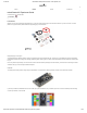
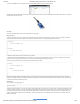
(2) Breadboard - Self-Adhesive (White)
PRT-12002
This is your tried and true white solderless breadboard. It has 2 power buses, 10 columns, and 30 rows - a total of 400 tie in points. All pins are sp…
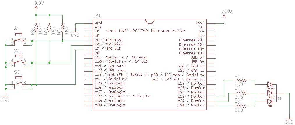
Schematic
Click on schematic to view larger image.
Connections
Connect the LPC1768 to the buttons and LED in the following fashion.
Polarized
Components
Pay special attention to the component’s markings indicating how to place it on the breadboard. Polarized components can only be connected
to a circuit in one direction. Polarized components are highlighted with a yellow warning triangle in the table below.
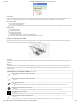
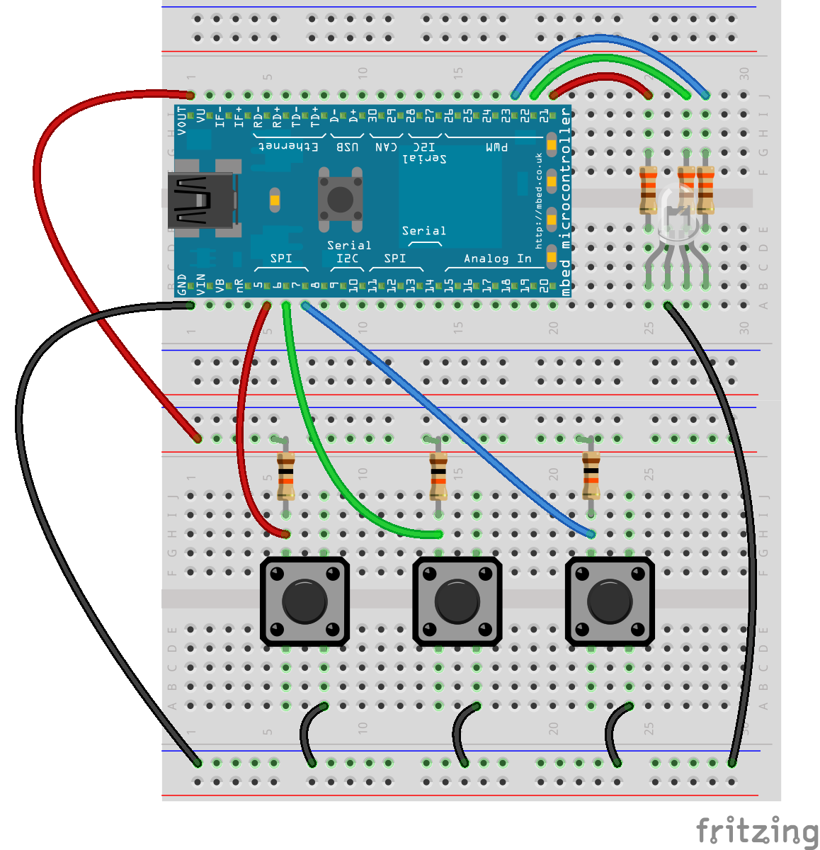
Fritzing Diagram
Be careful with the direction of the LED (polarity matters!). In the diagram, the flat edge (see the Tips section below) is facing to the left.
Note that the colors of the wires do not matter. Feel free to use any color you like! Do not worry if your kit does not have 5 black wires.
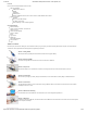
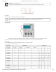
Hookup Table
Place the LPC1768 in the first breadboard with pin VOUT in position i1 and pin 20 in position b20.
Connect the rest of the components as follows:
Component Breadboard 1 Breadboard 2
RGB LED b25 (RED) b26 (GND) b27 (GREEN) b28 (BLUE)
330 Resistor e25 g25
330 Resistor e27 g27
330 Resistor e28 g28
Pushbutton d6 d8 g6 g8
Pushbutton d14 d16 g14 g16
Pushbutton d22 d24 g22 g24
10k Resistor i6 ( + )
10k Resistor i14 ( + )
10k Resistor i22 ( + )
Jumper Wire j1 ( + )
Jumper Wire a1 ( - )
Jumper Wire a5 h6