
Guide

1/12/2018 mbed Starter Kit Experiment Guide - learn.sparkfun.com
https://learn.sparkfun.com/tutorials/mbed-starter-kit-experiment-guide/all 45/65
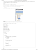
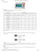
Fritzing Diagram
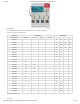
Hookup Table
Place the LPC1768 in a breadboard with pin VOUT in position i1 and pin 20 in position b20.
Connect the rest of the components as follows:
Component Breadboard
MicroSD Transflash Breakout* g24 (CS) g25 (DI) g26 (VCC) g27 (SCK) g28 (GND) g29 (DO)
Temperature Sensor - TMP36 c28 (V+) c29 (SIGNAL) c30 (GND)
Jumper Wire j1 ( + )
Jumper Wire a1 ( - )
Jumper Wire a5 f25
Jumper Wire a6 f29
Jumper Wire a7 f27
Jumper Wire a8 f24
Jumper Wire ( - ) f28
Jumper Wire ( + ) f26
Jumper Wire a15 a29
Jumper Wire ( - ) a30
Jumper Wire ( + ) a28
* Pins not listed are not used.
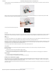
Tips
Make sure you face the TMP36 temperature sensor the correct way. The flat side of the black package body is considered the front. See this tutorial to learn
more about polarity.
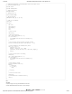
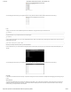
The Code
We plan to read an analog voltage from the sensor, and to do this, we rely on the mbed’s analog-to-digital converter (ADC) built into the chip. Every time we read
this value, we convert it to an actual temperature in degrees Celsius and log it to the SD card. Additionally, we will be using the mbed’s built-in USB-to-Serial
device to print our logged values to a console on our computer.
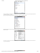
Software
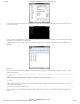
Windows
If you are on Windows, we will be relying on a program called “PuTTY.” You are also welcome to use any number of other serial terminal programs, such as
CoolTerm or Realterm.
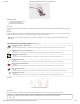
Navigate to the PuTTY homepage and download putty.exe.