
Guide

1/12/2018 mbed Starter Kit Experiment Guide - learn.sparkfun.com
https://learn.sparkfun.com/tutorials/mbed-starter-kit-experiment-guide/all 31/65
mbed Starter Kit - Part 5: Internet Clock SparkFun Wish List
Heads up! For anyone ordering the parts separately from the SparkFun mbed starter kit, you will need to solder the header to the RJ45 MagJack's
breakout board.
SparkFun RJ45 MagJack Breakout
BOB-13021
This is the SparkFun RJ45 MagJack Breakout, a simple board that will provide you with a way to put an ethernet port into your breadboard. The SparkFun…
mbed - LPC1768 (Cortex-M3)
DEV-09564
The mbed microcontroller is an ARM processor, a comprehensive set of peripherals and a USB programming and communication interface provided in a small…
Serial Miniature LCD Module - 1.44" (uLCD-144-G2 GFX)
LCD-11377
The µLCD-144-G2(GFX) is a compact and cost effective display module using the latest state of the art LCD (TFT) technology with an embedded GOLDELOX-…
Jumper Wires Standard 7" M/M - 30 AWG (30 Pack)
PRT-11026
If you need to knock up a quick prototype there's nothing like having a pile of jumper wires to speed things up, and let's face it: sometimes you want…
Break Away Headers - Straight
PRT-00116
A row of headers - break to fit. 40 pins that can be cut to any size. Used with custom PCBs or general custom headers.**Features: *** Pin Style: Squar…
(2) Breadboard - Self-Adhesive (White)
PRT-12002
This is your tried and true white solderless breadboard. It has 2 power buses, 10 columns, and 30 rows - a total of 400 tie in points. All pins are sp…
CAT 6 Cable - 3ft
CAB-08915
This 3ft Category 6 (CAT 6) Ethernet cable is the solution to your internet working needs. With a speed of up to 500MHz you can connect to your LAN/WA…
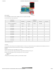
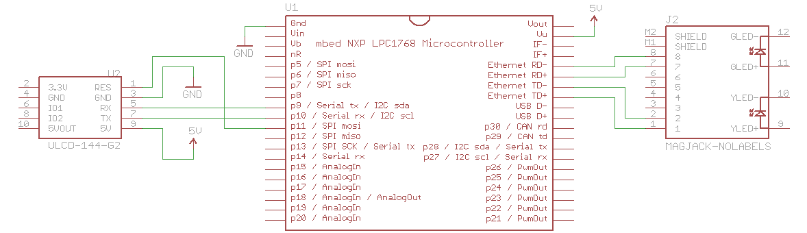
Schematic
Click on schematic to view larger image.
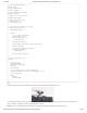
Connections
Connect the LPC1768 to the LCD and Ethernet jack in the following fashion. Note that the LCD uses the same connections as in Part 3.
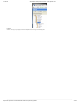
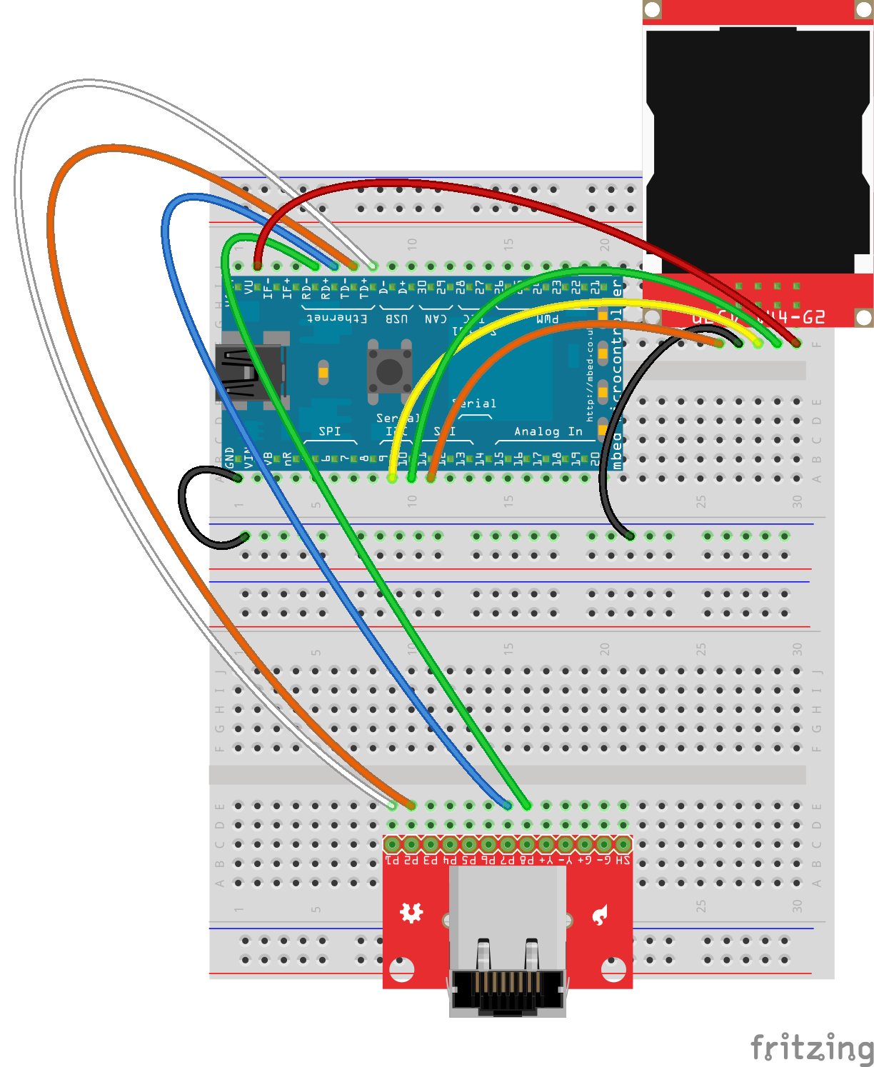
Fritzing Diagram
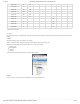
Hookup Table
Place the LPC1768 in the first breadboard with pin VOUT in position i1 and pin 20 in position b20.
Connect the rest of the components as follows:
Component Breadboard 1 Breadboard 2
uLCD-144-G2* h26 (RES) h27 (GND) h28 (RX) h29 (TX) h30 (+5V)
RJ45 MagJack Breakout* c9 (P1) c10 (P2) c15 (P7) c16 (P8)