
Guide

1/12/2018 mbed Starter Kit Experiment Guide - learn.sparkfun.com
https://learn.sparkfun.com/tutorials/mbed-starter-kit-experiment-guide/all 21/65
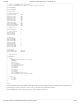
Click on schematic to view larger image.
Connections
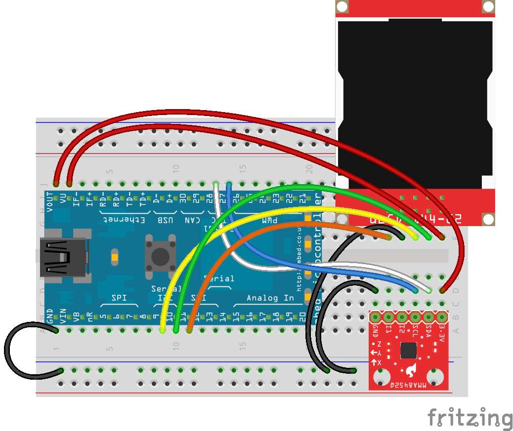
Connect the LPC1768 to the LCD and accelerometer in the following fashion. Note that the LCD uses the same connections as in Part 3.
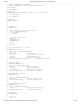
Fritzing Diagram
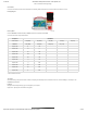
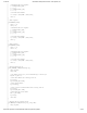
Hookup Table
Place the LPC1768 in a breadboard with pin VOUT in position i1 and pin 20 in position b20.
Connect the rest of the components as follows:
Component Breadboard
uLCD-144-G2* h26 (RES) h27 (GND) h28 (RX) h29 (TX) h30 (+5V)
MMA8452* b25 (GND) b28 (SCL) b29 (SDA) b30 (3.3V)
Jumper Wire j2 f30
Jumper Wire a1 ( - )
Jumper Wire a9 f28
Jumper Wire a10 f29
Jumper Wire a11 f26
Jumper Wire ( - ) f27
Jumper Wire ( - ) d25
Jumper Wire j14 d28
Jumper Wire j13 d29
Jumper Wire j1 d30
* Pins not listed are not used.
The Code
We will be building on the previous tutorial. In addition to importing an mbed library from the Cookbook for the LCD, we will be building our own library for the
MMA8452Q accelerometer.
Libraries
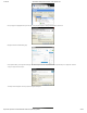
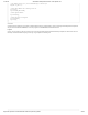
Navigate to the developer.mbed.org, login, and navigate to your Compiler.
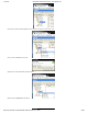
Right-click on “My Programs” and create a new program.