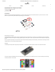
/12/2018 mbed Starter Kit Experiment Guide - learn.sparkfun.com SHOP LEARN BLOG SUPPORT mbed Starter Kit Experiment Guide CONTRIBUTORS: FAVORITE SHAWNHYMEL 5 Introduction Whether you have just purchased the mbed Starter Kit or you are just checking out this page to see what mbed is all about, you are in for a treat. The mbed platform is a project created by ARM to assist with rapid prototyping on microcontrollers. SparkFun mbed Starter Kit KIT-14458 Rapid prototyping? Come again? Yes.
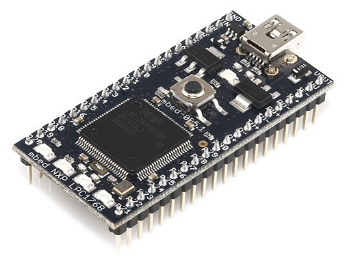
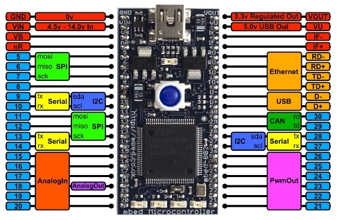
1/12/2018 mbed Starter Kit Experiment Guide - learn.sparkfun.com Features Here are the technical specifications of the LPC1768: NXP LPC1768 MCU ARM® Cortex™-M3 Core 96MHz 32KB RAM 512KB FLASH Ethernet, USB Host orDevice, SPI x2, I2C x2, UART x3, CAN, PWM x6, ADC x6, GPIO Platform form factor 54x26mm 40-pin 0.1" pitch DIP package 5V USB or 4.
1/12/2018 mbed Starter Kit Experiment Guide - learn.sparkfun.com Tutorial 8 - Temperature Logging Want to see how the temperature varies over time in an area? We connect a temperature sensor and an SD card to the mbed to log temperature measurements. Tutorial 9 - PWM Sounds Let’s make some music! We can use pulse-width modulation (PWM) to control sounds out of a speaker or set of headphones.
1/12/2018 mbed Starter Kit Experiment Guide - learn.sparkfun.com Double-click on the MBED.HTM link, which should open up a webpage that asks you to create a new mbed account. IMPORTANT: Some older versions of the LPC1768 contain a link to a page that does not exist. If you get an error, navigate to mbed's Account Signup page to create an account. Click “Signup” and follow the prompts to create a new mbed.org account. Once you have created an account, navigate to developer.mbed.org.
1/12/2018 mbed Starter Kit Experiment Guide - learn.sparkfun.com Click “OK” and you will see your new program appear in your workspace. Click on “main.cpp” in the pane on the left side to open up our C++ program. The code imports the mbed.h library, configures the pin for the LPC1768’s onboard LED to output, and blinks the LED forever. It has been copied here for reference. #include "mbed.h" DigitalOut myled(LED1); int main() { while(1) { myled = 1; wait(0.2); myled = 0; wait(0.
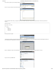
1/12/2018 mbed Starter Kit Experiment Guide - learn.sparkfun.com If you look in the MBED drive, you should see two files: the original MBED.HTM link and your new blinky program. Without disconnecting the USB cable, press the button in the middle of the LPC1768. You should see the bottom left LED begin to flash off and on. The blinking LED shows that your code is running! Concepts This is our first program with the mbed, so we should talk about what is going on.
1/12/2018 mbed Starter Kit Experiment Guide - learn.sparkfun.com Going Further This is just the beginning! You got a taste of the mbed Compiler and built your first program. Now that you understand how to use the mbed Compiler, we will move on to more advanced topics and show you how to connect other pieces of hardware to make the LPC1768 do fun and interesting things.
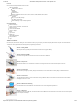
1/12/2018 mbed Starter Kit Experiment Guide - learn.sparkfun.com (2) Breadboard - Self-Adhesive (White) PRT-12002 This is your tried and true white solderless breadboard. It has 2 power buses, 10 columns, and 30 rows - a total of 400 tie in points. All pins are sp… Schematic Click on schematic to view larger image. Connections Connect the LPC1768 to the buttons and LED in the following fashion.
1/12/2018 mbed Starter Kit Experiment Guide - learn.sparkfun.com Jumper Wire a6 h14 Jumper Wire a7 h22 Jumper Wire j20 j25 Jumper Wire j19 j27 Jumper Wire j18 j28 Jumper Wire a26 (-) Jumper Wire a8 (-) Jumper Wire a16 (-) Jumper Wire a24 (-) Tips Pushbuttons The leads across each other on the pushbuttons are always connected to each other. The leads on the same side are only connected when button is pressed.
1/12/2018 mbed Starter Kit Experiment Guide - learn.sparkfun.com 330 ohm resistors 10k ohm resistors are given by the color code “brown black orange.” 10k ohm resistors The Code If you have not done so already, sign into your mbed.org account. Go to the Compiler and create a new program. Leave the template as “Blinky LED Hello World” and give it a name such as “rgb_buttons.” Click OK and wait for your new program to be created. Once that is done, click “main.cpp” under your project folder (e.g.
1/12/2018 mbed Starter Kit Experiment Guide - learn.sparkfun.com #include "mbed.h" // Define buttons InterruptIn button_red(p5); InterruptIn button_green(p6); InterruptIn button_blue(p7); // Define LED colors PwmOut led_red(p21); PwmOut led_green(p22); PwmOut led_blue(p23); // Interrupt Service Routine to increment the red color void inc_red() { float pwm; // Read in current PWM value and increment it pwm = led_red.read(); pwm += 0.1f; if (pwm > 1.0f) { pwm = 0.0f; } led_red.
1/12/2018 mbed Starter Kit Experiment Guide - learn.sparkfun.com Concepts What is going on in our program? We should understand a few concepts about our seemingly simple RGB LED and button program that are crucial in embedded systems. Pull-up Resistors We use 10kΩ pull-up resistors to prevent shorting 3.3V to ground whenever we push one of the buttons. Additionally, the pull-up resistors on the microcontroller (LPC1768) pin holds the pin at 3.3V by default until the button is pushed.
1/12/2018 mbed Starter Kit Experiment Guide - learn.sparkfun.com 18. Arduino for Production! AVR Atmega32 - Intro to Interrupts PWM To control the brightness of the LEDs, we do not vary the current going into the LED. Rather, we rapidly turn the LED off and on to give the appearance of a dimmer LED. This is known as “Pulse-Width Modulation” (PWM). Note that we are flipping the LED off and on so fast that generally our eyes cannot see the flickering.
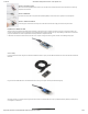
1/12/2018 mbed Starter Kit Experiment Guide - learn.sparkfun.com Suggested Reading Serial Communication The Circuit This circuit can be made with parts in the SparkFun mbed Starter Kit. Also, keep in mind that the LPC1768 box contains a USB mini-B cable for programming and power. Parts List To follow this experiment, you would will need the following materials if you did not order the SparkFun mbed starter kit. You may not need everything though depending on what you have.
1/12/2018 mbed Starter Kit Experiment Guide - learn.sparkfun.com Hookup Table Place the LPC1768 in a breadboard with pin VOUT in position i1 and pin 20 in position b20. Connect the rest of the components as follows: Component Breadboard uLCD-144-G2* h26 (RES) h27 (GND) Jumper Wire j2 f30 Jumper Wire a1 (-) Jumper Wire a9 f28 Jumper Wire a10 f29 Jumper Wire a11 f26 Jumper Wire (-) f27 h28 (RX) h29 (TX) h30 (+5V) * Pins not listed are not used.
1/12/2018 mbed Starter Kit Experiment Guide - learn.sparkfun.com Since the import process imported only the 4DGL-uLCD-SE library, we need to add the mbed library. In the Compiler, right-click on the “ulcd_demo” project, highlight “Import Library…” and select “From Import Wizard…” That will bring you to the Import Wizard page.
1/12/2018 mbed Starter Kit Experiment Guide - learn.sparkfun.com You will be prompted to name your new file. Call it “main.cpp” and click the “OK” button. The Compiler will automatically open the new main.cpp in the workspace. Enter the following code so that we can test out our 4D serial LCD. https://learn.sparkfun.
1/12/2018 mbed Starter Kit Experiment Guide - learn.sparkfun.com // Demo for the uLCD-144-G2 based on the work by Jim Hamblen #include "mbed.h" #include "uLCD_4DGL.h" // TX, RX, and RES pins uLCD_4DGL uLCD(p9,p10,p11); int main() { int int int int x; y; radius; vx; // Set our UART baudrate to something reasonable uLCD.baudrate(115200); // Change background color (must be called before cls) uLCD.background_color(WHITE); // Clear screen with background color uLCD.
1/12/2018 mbed Starter Kit Experiment Guide - learn.sparkfun.com Concepts We touched on a few important concepts in this tutorial that you may want to understand. Serial Communications To communicate between the mbed and the LCD, we are relying on a protocol known as UART. While you can create a program that emulates UART, it is far easier to rely on the mbed’s built-in UART hardware peripherals.
1/12/2018 mbed Starter Kit Experiment Guide - learn.sparkfun.
1/12/2018 mbed Starter Kit Experiment Guide - learn.sparkfun.com Click on schematic to view larger image. Connections Connect the LPC1768 to the LCD and accelerometer in the following fashion. Note that the LCD uses the same connections as in Part 3. Fritzing Diagram Hookup Table Place the LPC1768 in a breadboard with pin VOUT in position i1 and pin 20 in position b20.
1/12/2018 mbed Starter Kit Experiment Guide - learn.sparkfun.com Give your program an appropriate name (such as “ulcd_accel”), keep the Template as “Blinky LED Hello World,” and click OK. Navigate to the 4DGL-uLCD-SE library page. Click “Import this library” on the right side of the page. You will be brought to the mbed Compiler and asked to import the library. For “Target Path,” select our “ulcd_accel” project and click “Import.
1/12/2018 mbed Starter Kit Experiment Guide - learn.sparkfun.com Now, we get to create our own library! Right-click on the program in the left pane and select “New Library…” Name your library “MMA8452Q” and click OK. Right-click on the newly created library and select “New File…” Name your new file “MMA8452Q.h” and click OK. https://learn.sparkfun.
1/12/2018 mbed Starter Kit Experiment Guide - learn.sparkfun.com Repeat the same file creation process to make another file: “MMA8452Q.cpp”. Your project folder should contain a main.cpp, the mbed library, the 4DGL-uLCDSE library, and our newly created MMA8452Q library (with our blank .h and .cpp files). Click on the “MMA8452Q.h” file to open up the blank header (.h) file. Copy the following code into the file. https://learn.sparkfun.
1/12/2018 mbed Starter Kit Experiment Guide - learn.sparkfun.com // Library for our MMA8452Q 3-axis accelerometer // Based on the MMA8452Q Arduino Library by Jim Lindblom (SparkFun Electronics) #ifndef MMA8452Q_H #define MMA8452Q_H #include "mbed.
1/12/2018 mbed Starter Kit Experiment Guide - learn.sparkfun.com // Library for our MMA8452Q 3-axis accelerometer // Based on the MMA8452Q Arduino Library by Jim Lindblom (SparkFun Electronics) #include "mbed.h" #include "MMA8452Q.
1/12/2018 mbed Starter Kit Experiment Guide - learn.sparkfun.
1/12/2018 mbed Starter Kit Experiment Guide - learn.sparkfun.com // I2C address are bits [6..1] in the transmitted byte, so we shift by 1 dev_addr = m_addr << 1; // Write device address with a trailing 'write' bit m_i2c.start(); m_i2c.write(dev_addr & 0xFE); // Write register address m_i2c.write(reg); // Write the data to the register m_i2c.write(data); m_i2c.stop(); } Click “Save”. And that’s it! We just created our very first library in mbed.
1/12/2018 mbed Starter Kit Experiment Guide - learn.sparkfun.com // Demo for the uLCD-144-G2 and MMA8452Q 3-axis accelerometer #include "mbed.h" #include "MMA8452Q.h" #include "uLCD_4DGL.h" // Graphic LCD - TX, RX, and RES pins uLCD_4DGL uLCD(p9,p10,p11); // Accelerometer - SDA, SCL, and I2C address MMA8452Q accel(p28, p27, 0x1D); int main() { // Initialize uLCD uLCD.baudrate(115200); uLCD.background_color(BLACK); uLCD.cls(); // Initialize accelerometer accel.
1/12/2018 mbed Starter Kit Experiment Guide - learn.sparkfun.com I2C (or “Inter-Integrated Circuit”) is a communications protocol built by Philips in the 1980s. As I2C is a bus protocol, it allows for multiple masters and multiple devices to reside on the same bus and relies on addresses to communicate to specific devices. In our example, we used mbed’s I2C library to talk to the accelerometer. To read more about the history of I2C, see this Wikipedia article.
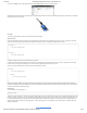
1/12/2018 mbed Starter Kit Experiment Guide - learn.sparkfun.com Heads up! For anyone ordering the parts separately from the SparkFun mbed starter kit, you will need to solder the header to the RJ45 MagJack's breakout board. mbed Starter Kit - Part 5: Internet Clock SparkFun Wish List SparkFun RJ45 MagJack Breakout BOB-13021 This is the SparkFun RJ45 MagJack Breakout, a simple board that will provide you with a way to put an ethernet port into your breadboard.
1/12/2018 mbed Starter Kit Experiment Guide - learn.sparkfun.com Jumper Wire j2 f30 Jumper Wire a1 (-) Jumper Wire a9 f28 Jumper Wire a10 f29 Jumper Wire a11 f26 Jumper Wire (-) f27 Jumper Wire j5 e16 Jumper Wire j6 e15 Jumper Wire j7 e10 Jumper Wire j8 e9 * Pins not listed are not used. The Code We will be relying heavily on pre-built libraries for this project. We need the same LCD library from the previous two tutorials as well as mbed’s Ethernet and NTP libraries.
1/12/2018 mbed Starter Kit Experiment Guide - learn.sparkfun.com // Internet Clock with LCD based on the work by Jim Hamblen and Tyler Lisowski #include #include #include #include "mbed.h" "EthernetInterface.h" "NTPClient.h" "uLCD_4DGL.h" // Parameters char* domain_name = "0.uk.pool.ntp.
1/12/2018 mbed Starter Kit Experiment Guide - learn.sparkfun.com Concepts Connecting something to the Internet opens up a whole new world. There is a lot going on to communicate to a remote server, so we recommend looking into a few concepts to familiarize yourself with how the Internet works. OSI Model Ethernet is just one small component in making devices talk over the Internet. Many protocols make up Internet communications and can be thought of like an onion.
1/12/2018 mbed Starter Kit Experiment Guide - learn.sparkfun.com IMPORTANT: You will need a USB keyboard for this tutorial. Suggested Reading USB Overview Multithreading The Circuit This circuit can be made with parts in the SparkFun mbed Starter Kit. Also, keep in mind that the LPC1768 box contains a USB mini-B cable for programming and power. Parts List To follow this experiment, you would will need the following materials if you did not order the SparkFun mbed starter kit.
1/12/2018 mbed Starter Kit Experiment Guide - learn.sparkfun.com Hookup Table Place the LPC1768 in a breadboard with pin VOUT in position i1 and pin 20 in position b20.
1/12/2018 mbed Starter Kit Experiment Guide - learn.sparkfun.com Program Click on “main.cpp” in your project, remove the template code, and copy in the following code. https://learn.sparkfun.
1/12/2018 mbed Starter Kit Experiment Guide - learn.sparkfun.com // USB host keyboard and LCD demo #include "mbed.h" #include "USBHostKeyboard.h" #include "uLCD_4DGL.h" // LED to demonstrate multi-threading DigitalOut led(LED1); // Graphic LCD - TX, RX, and RES pins uLCD_4DGL uLCD(p9,p10,p11); // Callback function from thread void onKey(uint8_t key) { uLCD.
1/12/2018 mbed Starter Kit Experiment Guide - learn.sparkfun.com NOTE #2: The USBHost library is in beta and has some issues connecting USB devices sometimes. Not all keyboards will work with this demo. Also, if you try typing too fast, you will see repeat keys. This is because the mbed does not process two simultaneous key presses correctly. Concepts We covered two important concepts in this tutorial: USB and threading. Both create a unique set of opportunities for embedded systems.
1/12/2018 mbed Starter Kit Experiment Guide - learn.sparkfun.com Suggested Reading USB Overview USB Human Interface Device (HID) The Circuit This circuit can be made with parts in the SparkFun mbed Starter Kit. Also, keep in mind that the LPC1768 box contains a USB mini-B cable for programming and power. Parts List To follow this experiment, you would will need the following materials if you did not order the SparkFun mbed starter kit. You may not need everything though depending on what you have.
1/12/2018 mbed Starter Kit Experiment Guide - learn.sparkfun.com Hookup Table Place the LPC1768 in the first breadboard with pin VOUT in position i1 and pin 20 in position b20.
1/12/2018 mbed Starter Kit Experiment Guide - learn.sparkfun.com In order to make the mbed act like a USB mouse for this walkthrough, we will rely on mbed’s USBDevice library. This library contains all the necessary functions to enumerate as a USB device to a computer and function as a mouse. Libraries Navigate to the mbed.org, login, and navigate to your Compiler. Create a new program with the “Blinky LED Hello World” template. Name it something like “usb_device.
1/12/2018 mbed Starter Kit Experiment Guide - learn.sparkfun.com Compile the program and copy the downloaded file to the mbed. Disconnect the USB mini-B that you used to program your mbed and connect it into the USB mini-B breakout board. Make sure that the other end of the USB cable is plugged into your computer and press the mbed’s restart button. Your computer should tell you that a USB input device has been detected. Start pressing the four buttons on the breadboard.
1/12/2018 mbed Starter Kit Experiment Guide - learn.sparkfun.com Suggested Reading How does a temperature sensor work? Serial Peripheral Interface (SPI) mbed’s SD Card File System Library The Circuit This circuit can be made with parts in the SparkFun mbed Starter Kit. Also, keep in mind that the LPC1768 box contains a USB mini-B cable for programming and power. Parts List To follow this experiment, you would will need the following materials if you did not order the SparkFun mbed starter kit.
1/12/2018 mbed Starter Kit Experiment Guide - learn.sparkfun.com Fritzing Diagram Hookup Table Place the LPC1768 in a breadboard with pin VOUT in position i1 and pin 20 in position b20.
1/12/2018 mbed Starter Kit Experiment Guide - learn.sparkfun.com There is no installation process, so just copy putty.exe to some place you will remember, such as your desktop. Additionally, we need to install a Serial Port driver if you are on Windows. Navigate to mbed’s Windows serial configuration page and download the latest driver. Double click the downloaded file and follow the on-screen instructions to install the driver.
1/12/2018 mbed Starter Kit Experiment Guide - learn.sparkfun.com // Temperature logging demo - record temperatures to SD card and print them to // the console every 10 seconds #include "mbed.h" #include "SDFileSystem.
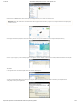
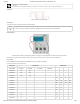
1/12/2018 mbed Starter Kit Experiment Guide - learn.sparkfun.com Click on “Device Manager.” You should see the Device Manager open up. Click to expand “Ports (COM & LPT).” Make a note of which COM port is listed as the “mbed Serial Port” (COM12, in this example). Note: If you do not see the mbed Serial Port listed, you need to install (or re-install) the mbed Windows serial driver. Double-click the putty.exe icon to start PuTTY. In the left pane, click “Terminal” to configure PuTTY.
1/12/2018 mbed Starter Kit Experiment Guide - learn.sparkfun.com Press the mbed’s reset button. You should see some text appear in the console. Wait 10 seconds while the mbed makes some temperature readings, and it will print them to the terminal. If you see a message like “ERROR: Could not open file for writing!” it means that you do not have an SD card plugged in, you do not have the SD Card breakout connected properly, or the SD card is not formatted properly.
1/12/2018 mbed Starter Kit Experiment Guide - learn.sparkfun.com You can also plug the SD card into your computer and open the “temp_data.txt” file with a text editor (located in the SD card’s root directory). Linux To begin, we need to find out which USB serial port the mbed is attached to. Unplug the mbed. Open a terminal and enter: ls /dev/tty* Plug the mbed back into your computer and enter the command again: ls /dev/tty* A new tty device should appear. In my case, I saw “/dev/ttyACM0” show up.
1/12/2018 mbed Starter Kit Experiment Guide - learn.sparkfun.com With the rise of the graphical user interface (GUI), such as Windows, terminal programs became emulated inside of the GUI and usually only reserved for more advanced functions. Because many low-power embedded systems, such as the LPC1768, are incapable of running a GUI, we rely on a serial terminal to communicate with the device. Check out our tutorial on Serial Terminal Emulators) for more info.
1/12/2018 mbed Starter Kit Experiment Guide - learn.sparkfun.com It’s always a good idea to close a file when you are done with it! Otherwise, you might corrupt the file (or, worse, the filesystem) if your program starts to behave unexpectedly with a file still open. We can perform a similar procedure to read from a file. In our example, we use fgetc() to read characters from the file one at a time.
1/12/2018 mbed Starter Kit Experiment Guide - learn.sparkfun.
1/12/2018 mbed Starter Kit Experiment Guide - learn.sparkfun.com This demo is simple! We don’t need any libraries. Navigate to the mbed.org, login, and navigate to your Compiler. Create a new program with the “Blinky LED Hello World” template. Name it something like “pwm_song.” Click on “main.cpp” in your project, remove the template code, and copy in the following code. // Plays a familiar melody using PWM to the headphones. To find the frequencies // of notes, see http://en.wikipedia.
1/12/2018 mbed Starter Kit Experiment Guide - learn.sparkfun.com Concepts Much like in our other PWM tutorial, we relied on pulse-width modulation to emulate an analog signal (sound, this time). We also connected a peripheral that allowed us to convert electrical signals into sound: a speaker (or headphones, but these are nothing more than tiny speakers that wrap around your head). PWM for Sound Much like in Part 2, we used a PWM to control the a signal.
1/12/2018 mbed Starter Kit Experiment Guide - learn.sparkfun.com Heads up! For anyone ordering the parts separately from the SparkFun mbed starter kit, you will need to solder the header to the microSD card's breakout board.
1/12/2018 mbed Starter Kit Experiment Guide - learn.sparkfun.com Hookup Table Place the LPC1768 in the first breadboard with pin VOUT in position i1 and pin 20 in position b20.
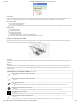
1/12/2018 mbed Starter Kit Experiment Guide - learn.sparkfun.com Jumper Wire Jumper Wire (-) a14 Jumper Wire j14 j17 (-) j19 * Pins not listed are not used. Tips Transistor Make sure you are using the 2N3904 transistor and not the temperature sensor! Note that the flat edge of the transistor is facing down in the Fritzing diagram. Speaker Notice that the speaker has the positive (+) and negative (-) pins labeled on the underside.
1/12/2018 mbed Starter Kit Experiment Guide - learn.sparkfun.com // Soundboard that plays 1 of 4 .wav files stored on the SD card based on 1 of // 4 buttons pressed #include "mbed.h" #include "wave_player.h" #include "SDFileSystem.h" // .wav files to play const char *filenames[4] = { "/sd/good_morning.wav", "/sd/questions.wav", "/sd/lack_discipline.wav", "/sd/stop_whining.
1/12/2018 mbed Starter Kit Experiment Guide - learn.sparkfun.com } } Run Insert the micro SD card into the USB to micro SD card adapter and insert the USB adapter into your computer. Copy the following .wav files to the SD’s root directory: good_morning.wav lack_discipline.wav questions.wav stop_whining.wav Remove the SD card from your computer and plug it into the breakout board on the soundboard project. Compile the program and copy the downloaded file to the mbed.
1/12/2018 mbed Starter Kit Experiment Guide - learn.sparkfun.com https://learn.sparkfun.
1/12/2018 mbed Starter Kit Experiment Guide - learn.sparkfun.com https://learn.sparkfun.
1/12/2018 mbed Starter Kit Experiment Guide - learn.sparkfun.com https://learn.sparkfun.
1/12/2018 mbed Starter Kit Experiment Guide - learn.sparkfun.com https://learn.sparkfun.
1/12/2018 mbed Starter Kit Experiment Guide - learn.sparkfun.com https://learn.sparkfun.

