
Data Sheet

MLX90640 32x24 IR array
Datasheet
Page 54 of 60
REVISION 11 – 3 AUGUST 2018
13.2.
13.2.13.2.
13.2. Using the device in “image mode”
Using the device in “image mode” Using the device in “image mode”
Using the device in “image mode”
In some applications may not be necessary to calculate the temperature but rather to have just and image (for
instance in machine vision systems). In this case it is not necessary to carry out all calculations which would save
computation time or allow the one to use weaker CPU.
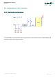
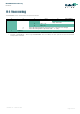
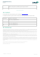
In order to get thermal image only following computation flow is to be used:
Figure 26 Calculation flow in thermal image mode
14. Application Comments
Significant contamination at the optical input side (sensor filter) might cause unknown additional filtering/distortion of the
optical signal and therefore result in unspecified errors.
IR sensors are inherently susceptible to errors caused by thermal gradients. There are physical reasons for these phenomena
and, in spite of the careful design of the MLX90640Bxx, it is recommended not to subject the MLX90640Bxx to heat transfer
and especially transient conditions.
The MLX90640Bxx is designed and calibrated to operate as a non-contact thermometer in settled conditions. Using the
thermometer in a very different way will result in unknown results.
Capacitive loading on an I
2
C can degrade the communication. Some improvement is possible with use of current sources
compared to resistors in pull-up circuitry. Further improvement is possible with specialized commercially available bus
accelerators. With the MLX90640Bxx additional improvement is possible by increasing the pull-up current (decreasing the
pull-up resistor values). Input levels for I
2
C compatible mode have higher overall tolerance than the I
2
C specification, but the
output low level is rather low even with the high-power I
2
C specification for pull-up currents. Another option might be to go
for a slower communication (clock speed), as the MLX90640Bxx implements Schmidt triggers on its inputs in I
2
C compatible
mode and is therefore not really sensitive to rise time of the bus (it is more likely the rise time to be an issue than the fall
time, as far as the I
2
C systems are open drain with pull-up).
Ambient temperature calculation (common for all pixels) - 11.2.2.3
Gain compensation - 11.2.2.5.1
IR data compensation – offset, VDD and Ta - 11.2.2.5.3
IR data gradient compensation - 11.2.2.7
Normalizing to sensitivity
-
11.2.2.8
Image (data) processing
Supply voltage value calculation (common for all pixels) - 11.2.2.2