
Data Sheet

MLX90640 32x24 IR array
Datasheet
Page 11 of 60
REVISION 11 – 3 AUGUST 2018
10.2.
10.2.10.2.
10.2. Communication protocol
Communication protocolCommunication protocol
Communication protocol
The device use I
2
C protocol with support of FM+ mode (up to 1MHz clock frequency) and can be only slave on the bus.
The SDA and SCL ports are 5V tolerant and the sensor can be directly connected to a 5V I
2
C network.
The slave address is programmable and can have up to 127 different slave addresses.
10.2.1.
10.2.1.10.2.1.
10.2.1. Low level
Low level Low level
Low level
10.2.1.1.
10.2.1.1.10.2.1.1.
10.2.1.1. Start / Stop conditions
Start / Stop conditionsStart / Stop conditions
Start / Stop conditions
Each communication session is initiated by a START condition and ends with a STOP condition. A START condition is
initiated by a HIGH to LOW transition of the SDA while a STOP is generated by a LOW to HIGH transition. Both changes must
be done while the SCL is HIGH.
10.2.1.2.
10.2.1.2.10.2.1.2.
10.2.1.2. Device addressing
Device addressingDevice addressing
Device addressing
The master is addressing the slave device by sending a 7-bit slave address after the START condition. The first seven bits are
dedicated for the address and the 8
th
is Read/Write (R/W) bit. This bit indicates the direction of the transfer:
• Read (HIGH) means that the master will read the data from the slave
• Write (LOW) means that the master will send data to the slave
10.2.1.3.
10.2.1.3.10.2.1.3.
10.2.1.3. Acknowledge
AcknowledgeAcknowledge
Acknowledge
During the 9
th
clock following every byte transfer the transmitter releases the SDA line. The receiver acknowledges
(ACK) receiving the byte by pulling SDA line to low or does not acknowledge (NoACK) by letting the SDA ‘HIGH’.
10.2.1.4.
10.2.1.4.10.2.1.4.
10.2.1.4. I
II
I
2
22
2
C command format
C command formatC command format
C command format
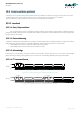
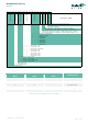
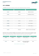
Figure 4 I
2
C write command format (default SA=0x33 is used)
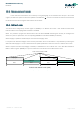
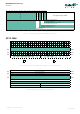
Figure 5 I
2
C read command format (default SA=0x33 is used)
SCL
SDA
10 1 0 A AS A A A
P
Slave address
W1 10
MSByte address LSByte address MSByte data LSByte data
I
2
C write
SCL
SDA
10 1 0 A AS A A
NAK P
Slave address
W1 10
MSByte address LSByte address MSByte data LSByte data
I
2
C read
S 10 1 0
R
1 10 A
Slave address