
Data Sheet

97 : circuit 5b
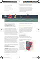
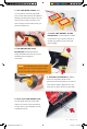
. CUT TWO MORE STRIPS that
are 1.25 inches (3.175cm) long and ¾
inch (1.9cm) wide. Remove the adhesive
backing, and attach the strips to the two
motors. Be sure that your motors are
mirror images of each other when you
attach the Dual Lock.
. PRESS THE MOTORS TO THE
BASEPLATE, connecting the two Dual
Lock surfaces. Try to get the motors as
straight as possible so your robot will
drive straight.
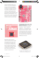
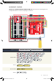
. THE BOTTOM OF YOUR
BASEPLATE should look like the
image. Remember that the two motors
should be mirror images of
each other.
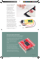
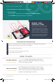
. ATTACH THE WHEELS by sliding
them onto the plastic shafts on the
gearmotor. The shaft is flat on one side, as
is the wheel coupler. Align the two, and
then press to fit the wheel onto the shaft.
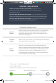
. LAST, CLIP THE BINDER CLIP
onto the back end of the robot. This
will act as a caster as the robot drives
around. Once you’re finished, it’s time
to build the circuit.
NOTE: You will likely have a piece of Dual
Lock in the center of your baseplate from
Project 4. It will be used in the next circuit.
SIK v4 Book Oct 13.indb 97 10/18/17 10:02 AM