
Data Sheet

91 : circuit 5a
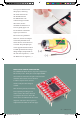
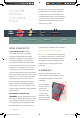
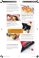
Once you’re finished with
this project, removing
the motor driver from
the breadboard can
be difficult due to its
numerous legs. To make
this easier, use the
included screwdriver as a
lever to gently pry it out.
Be careful not to bend the
legs as you remove it.
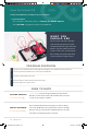
The motors are polarized.
However, motors are unique
in that they will still work
when the two connections are
reversed. They will just spin
in the opposite direction when
hooked up backward. To keep
things simple, always think of
the red wire as positive ( + ) and
the black wire as negative ( - ).
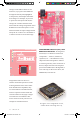
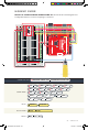
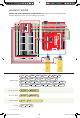
MEET YOUR MOTOR CONTROLLER.
The TB6612FNG Motor Driver may look complicated,
but it’s easy to use. Three pins on the right (PWMA,
A12 and A11) control the two pins on the left (A01
and A02). The same is true for channel
B. Motors require more current,
which is why the VIN voltage is
needed.
Most ICs have polarity and usually
have a polarity marking in one
of the corners. The motor driver is
no exception. Be sure to insert the
motor driver as indicated in the circuit
diagrams. The motor driver pins are
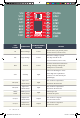
explained in the table on the next page.
SIK v4 Book Oct 13.indb 91 10/18/17 10:02 AM