
Data Sheet


54 : circuit 3a
NEW COMPONENTS
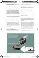
SERVO MOTORS: Regular DC motors
have two wires. When you hook the wires
up to power, the motor spins around and
around. Servo motors, on the other hand,
have three wires: one
for power, one for
ground and one for
signal. When you send
the right signal through
the signal wire, the
servo will move to a
specific angle and stay
there. Common servos rotate over a range
of about 0° to 180°. The signal that is sent is
a PWM signal, the same used to control the
RGB LED in Project 1.
Included with
your servo motor
you will find a
variety of motor
mounts that
connect to the
shaft of your servo. You may choose to
attach any mount you wish for this circuit.
It will serve as a visual aid, making it easier
to see the servo spin. The mounts will also
be used at the end of this project.
NEW CONCEPTS
DUTY CYCLE: Pulse-Width Modulation
(PWM) is a great way to generate servo
control signals. The length of time a PWM
signal is on is
referred to as
the duty cycle.
Duty cycle is
measured in
percentage.
Thus a duty cycle of 50 percent means the
signal is on 50 percent of the time. The
variation in the duty cycle is what tells the
servo which position to go to in its rotation.
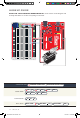
Circuit 3A: Servo
Motors
In this circuit, you will learn how to wire
a servo and control it with code. Servo
motors can be told to move to a specific
position and stay there. Low-cost servo
motors were originally used to steer RC
airplanes and cars, but they have become
popular for any project where precise
movement is needed.
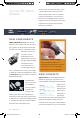
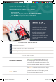
ATTACHING YOUR SERVO:
A strip of adhesive Dual Lock
TM
fastening tape is included in your kit.
Cut two pieces of it to temporarily
affix your servo to your baseplate.
YOU
NEED
POTENTIOMETER SERVO JUMPER WIRES SCISSORS
(NOT INCLUDED)
SIK v4 Book Oct 13.indb 54 10/18/17 10:00 AM