
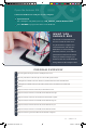
Data Sheet
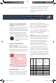

IOREF
RESET
RESET
7-15V
SCL
SDA
AREF
GND
13
12
~11
~10
~9
8
7
~6
~5
4
~3
2
1
0
TX
RX
13
3.3V
5V
GND
GND
VIN
A0
A1
A2
A3
A4
A5
POWER ANALOG IN
DIGITAL (PWM~)
ON
ISP
TX
RX
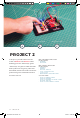
START SOMETHING
+ –
+ –
+ –
+ –
1
2
3
4
5
6
7
8
9
10
11
12
13
14
15
16
17
18
19
20
21
22
23
24
25
26
27
28
29
30
1
2
3
4
5
6
7
8
9
10
11
12
13
14
15
16
17
18
19
20
21
22
23
24
25
26
27
28
29
30
abcde fghij
abcde fghij
+ - + -
+ - + -
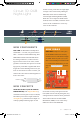
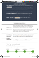
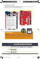
HOOKUP GUIDE
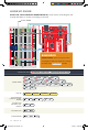
READY TO START HOOKING EVERYTHING UP? Check out the circuit diagram and
hookup table below to see how everything is connected.
VOLUME KNOB: Notice
that only two of the
potentiometer’s legs are
used in these circuits. The
potentiometer is acting as
a variable resistor, limiting
the amount of current
flowing to the speaker and
thus affecting the volume as
you turn the knob.
38 : circuit 2a
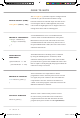
CONNECTION TYPES
REDBOARD CONNECTION
BREADBOARD CONNECTION
JUMPER WIRES
GND
to
GND(-)
D10
to
F1
E2
to
GND (-)
E1
to
F3
BUZZER
H1(+)
to
H3(-)
POTENTIOMETER
B1
+
B2
+
B3
REMEMBER!
POLARITY: The buzzer is polarized. To see which leg is positive and which is negative,
flip the buzzer over and look at the markings underneath. Keep track of which pin is
where, as they will be hard to see once inserted into the breadboard. There is also text
on the positive side of the buzzer, along with a tiny (+) symbol.
SIK v4 Book Oct 13.indb 38 10/18/17 10:00 AM