
Data Sheet

92 : circuit 5a
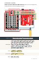
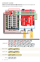
PIN
LABEL
FUNCTION
POWER/INPUT/
OUTPUT
NOTES
VM
Motor Voltage Power
This is where you provide power
for the motors (2.2V to 13.5V)
VCC
Logic Voltage Power
This is the voltage to power
the chip and talk to the
microcontroller (2.7V to 5.5V)
GND
Ground Power
Common Ground for both motor
voltage and logic voltage (all
GND pins are connected)
STBY
Standby Input
Allows the H-bridges to work
when high (has a pull-down
resistor, so it must actively be
pulled high)
AIN1/BIN1
Input 1 for
channels A/B
Input
One of the two inputs that
determine the direction
AIN2/BIN2
Input 2 for
channels A/B
Input
One of the two inputs that
determine the direction
PWMA/
PWMB
PWM input for
channels A/B
Input
PWM input that
controls the speed
A01/B01
Output 1 for
channels A/B
Output
One of the two outputs
to connect the motor
A02/B02
Output 2 for
channels A/B
Output
One of the two outputs to
connect the motor
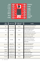
VM
VCC
GND
A01
A02
B02
B01
GND
PWMA
A12
A11
ST
BY
B11
B12
PWMB
GND
MOTOR
DRIVER
VM
VCC
GND
A01
A02
B02
B01
GND
PWMA
AIN2
AIN1
STBY
BIN1
BIN2
PWMB
GND