
Data Sheet

90 : circuit 5a
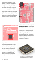
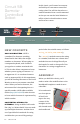
The guts of an integrated circuit,
visible after removing the top.
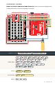
IOREF
RESET
RESET
7-15V
SCL
SDA
AREF
GND
13
12
~11
~10
~9
8
7
~6
~5
4
~3
2
1
0
TX
RX
13
3.3V
5V
GND
GND
VIN
A0
A1
A2
A3
A4
A5
POWER ANALOG IN
DIGITAL (PWM~)
ON
ISP
TX
RX
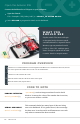
START SOMETHING
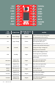
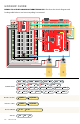
voltage on VIN will be about 4.6–5V.
However, if you power the RedBoard
through the barrel jack (highlighted
in the picture), the VIN pin will reflect
that voltage. For example, if you were
to power the barrel jack with 9V, the
voltage out on VIN would also be 9V.
Notice that the voltage range listed on the
RedBoard near the barrel jack is 7–15V.
This means that the input voltage should
always be at or above 7V or should be at
or below 15V. Never exceed this range.
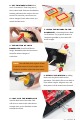
INTEGRATED CIRCUITS (ICS) AND
BREAKOUT BOARDS: An Integrated
Circuit (IC) is a collection of electronic
components — resistors, transistors,
capacitors, etc. — all stuffed into a tiny
chip and connected together to achieve
a common goal. They come in all sorts of
flavors, shapes and sizes. The chip that
powers the RedBoard, the ATmega328, is
an IC. The chip on the motor driver, the
TB6612FNG, is another IC.
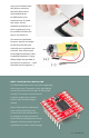
Integrated circuits are often too
small to work with by hand. To make
working with ICs easier and to make
them breadboard-compatible, they
are often added to a breakout board,
which is a printed circuit board that
connects all the IC’s tiny legs to larger
ones that fit in a breadboard. The
motor driver board in your kit is an
example of a breakout board.