
Data Sheet


4 : intro
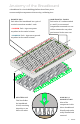
IOREF
RESET
RESET
7-15V
SCL
SDA
AREF
GND
13
12
~11
~10
~9
8
7
~6
~5
4
~3
2
1
0
TX
RX
13
3.3V
5V
GND
GND
VIN
A0
A1
A2
A3
A4
A5
POWER ANALOG IN
DIGITAL (PWM~)
ON
ISP
TX
RX
START SOMETHING
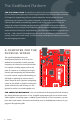
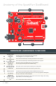
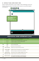
Anatomy of the SparkFun RedBoard
REDBOARD HARDWARE OVERVIEW
A
POWER IN
(BARREL JACK)
Can be used with either a 9V or 12V “wall-wart” or a battery pack.
B
POWER IN
(USB PORT)
Provides power and communicates with your board
when plugged into your computer via USB.
C
LED
(RX: RECEIVING)
Shows when the FTDI chip is receiving data bits from the computer.
D
LED
(TX: TRANSMITTING)
Shows when the FTDI chip is transmitting data bits to the computer.
E
ONBOARD LED
PIN D13
This LED, connected to digital pin 13, can be controlled
in your program and is great for troubleshooting.
F
PINS AREF,
GROUND, DIGITAL,
RX, TX, SDA, SCL
These pins can be used for inputs, outputs, power and ground.
G
POWER LED
Illuminated when the board is connected to a power source.
H
RESET BUTTON
A manual reset switch that will restart the RedBoard and your code.
I
ISP HEADER
This is the In-System Programming header. It is used to program the ATMega328
directly. It will not be used in this guide.
J
ANALOG IN,
VOLTAGE IN,
GROUND, 3.3 AND
5V OUT, RESET
The power bus has pins to power your circuits with various voltages. The analog
inputs allow you to read analog signals.
K
RFU
This stands for Reserved for Future Use.
A
B
C
D
E
F
H
I
J
G
K