
Data Sheet


HOOKUP GUIDE
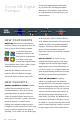
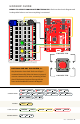
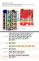
READY TO START HOOKING EVERYTHING UP? Check out the circuit diagram and
hookup table below to see how everything is connected.
43 : circuit 2b
IOREF
RESET
RESET
7-15V
SCL
SDA
AREF
GND
13
12
~11
~10
~9
8
7
~6
~5
4
~3
2
1
0
TX
RX
13
3.3V
5V
GND
GND
VIN
A0
A1
A2
A3
A4
A5
POWER ANALOG IN
DIGITAL (PWM~)
ON
ISP
TX
RX
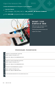
START SOMETHING
+ –
+ –
+ –
+ –
1
2
3
4
5
6
7
8
9
10
11
12
13
14
15
16
17
18
19
20
21
22
23
24
25
26
27
28
29
30
1
2
3
4
5
6
7
8
9
10
11
12
13
14
15
16
17
18
19
20
21
22
23
24
25
26
27
28
29
30
abcde fghij
abcde fghij
+ - + -
+ - + -
JUMPER WIRES
GND
to
GND(-)
D10
to
F1
D4
to
J18
D3
to
J24
D2
to
J30
E2
to
GND (-)
J16
to
GND (-)
J22
to
GND (-)
J28
to
GND (-)
E1
to
F3
BUZZER
H1(+)
to
H3(-)
PUSH BUTTONS
D16/D18
to
G16/18
D22/24
to
G22/24
D28/30
to
G28/30
POTENTIOMETER
B1
+
B2
+
B3
CONNECTED
CONNECTED
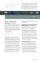
BUTTONS ARE NOT POLARIZED, but
they do merit a closer look. Each row of legs is
connected internally. When the button is pressed,
one row connects to the other, connecting all four
pins. If the button’s legs don’t line up with the
rows on the breadboard, rotate it 90 degrees.