
Data Sheet


33 : circuit 1d
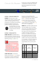
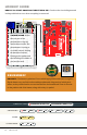
WHAT YOU
SHOULD SEE
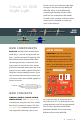
This sketch is not dissimilar from
the last. It reads the value from
the photoresistor, compares it to
a threshold value, and turns the
RGB LED on or off accordingly.
This time, however, we’ve added a
potentiometer back into the circuit.
When you twist the trimpot, you
should see the color of the RGB LED
change based on the trimpot’s value.
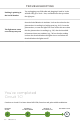
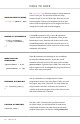
Open the Arduino IDE
Connect the RedBoard to a USB port on your computer.
Open the Sketch:
File > Examples > SIK_Guide_Code-V_4 > SIK_CIRCUIT_1D-RGB NIGHT LIGHT
Select UPLOAD to program the sketch on the RedBoard.
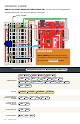
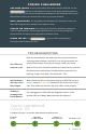
PROGRAM OVERVIEW
1
Store the light level from pin A0 in the variable photoresistor.
2
Store the potentiometer value from pin A1 in the variable potentiometer.
3
If the light level variable is above the threshold, call the function that turns the RGB LED off.
4
If the light level variable is below the threshold, call one of the color functions to turn the RGB
LED on.
5
If potentiometer is between 0 and 150, turn the RGB LED on red.
6
If potentiometer is between 151 and 300, turn the RGB LED on orange.
7
If potentiometter is between 301 and 450, turn the RGB LED on yellow.
8
If potentiometer is between 451 and 600, turn the RGB LED on green.
9
If potentiometer is between 601 and 750, turn the RGB LED on cyan.
10
If potentiometer is between 751 and 900, turn the RGB LED on blue.
11
If potentiometer is greater than 900, turn the RGB LED on magenta.