
Data Sheet

31 : circuit 1d
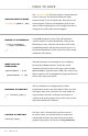
NEW COMPONENTS
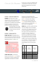
RGB LED: An RGB LED is actually three
small LEDs — one red, one green and one
blue — inside a normal LED housing. This
RGB LED has all the internal LEDs share
the same ground wire, so there are four
legs in total. To turn on one color, ensure
ground is connected, then power one of the
legs just as you would a regular LED. Don’t
forget the current-limiting resistors. If you
turn on more than one color at a time, you
will see the colors start to blend together to
form a new color.
NEW CONCEPTS
ANALOG OUTPUT (PULSE-WIDTH
MODULATION): The digitalWrite()
command can turn pins on (5V) or off (0V),
but what if you want to output 2.5V? The
analogWrite()
command can output 2.5
volts by quickly switching a pin on and
off so that it is only on 50 percent of the
time (50% of 5V is 2.5V). By doing this, any
voltage between 0 and 5V can be produced.
This is what is known as Pulse-Width
Modulation (PWM). It can create many
different colors on the RGB LED.
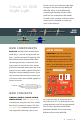
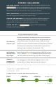
Circuit 1D: RGB
Night-Light
In this circuit, you’ll take the night-light
concept to the next level by adding an
RGB LED, which is three differently
colored Light-Emitting Diodes (LEDs)
built into one component. RGB stands
for Red, Green and Blue, and these three
colors can be combined to create any
color of the rainbow!
RED
COMMON (GND)
GREEN
BLUE
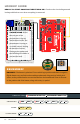
NEW IDEAS
PWM PINS: Only a few of the pins
on the RedBoard have the circuitry
needed to turn on and off fast enough
for PWM. These are pins 3, 5, 6, 9, 10
and 11. Each PWM pin is marked with
a ~ on the board. Remember, you can
only use
analogWrite()
on these
pins.
IOREF
RESET
RESET
7-15V
SCL
SDA
AREF
GND
13
12
~11
~10
~9
8
7
~6
~5
4
~3
2
1
0
TX
RX
13
3.3V
5V
GND
GND
VIN
A0
A1
A2
A3
A4
A5
POWER ANALOG IN
DIGITAL (PWM~)
ON
ISP
TX
RX
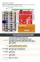
START SOMETHING
YOU
NEED
10k
100k
330
10k
100k
330
RGB LED PHOTORESISTOR 3 330Ω RESISTORS 10KΩ RESISTOR
12 JUMPER WIRES POTENTIOMETER