
Data Sheet


IOREF
RESET
RESET
7-15V
SCL
SDA
AREF
GND
13
12
~11
~10
~9
8
7
~6
~5
4
~3
2
1
0
TX
RX
13
3.3V
5V
GND
GND
VIN
A0
A1
A2
A3
A4
A5
POWER ANALOG IN
DIGITAL (PWM~)
ON
ISP
TX
RX
START SOMETHING
+ –
+ –
+ –
+ –
1
2
3
4
5
6
7
8
9
10
11
12
13
14
15
16
17
18
19
20
21
22
23
24
25
26
27
28
29
30
1
2
3
4
5
6
7
8
9
10
11
12
13
14
15
16
17
18
19
20
21
22
23
24
25
26
27
28
29
30
abcde fghij
abcde fghij
+ - + -
+ - + -
10k
100k
330
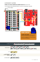
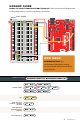
HOOKUP GUIDE
READY TO START HOOKING EVERYTHING UP? Check out the
circuit diagram and hookup table below to see how everything is connected.
21 : circuit 1b
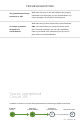
CONNECTION TYPES
REDBOARD CONNECTION
BREADBOARD CONNECTION
JUMPER WIRES
5V
to
5V
GND
to
GND (-)
A0
to
E26
E25
to
5V (+)
E27
to
GND (-)
E1
to
GND (-)
D13
to
J2
LED
A1(-)
to
A2(+)
330Ω RESISTOR
(ORANGE, ORANGE,
BROWN)
E2
to
F2
POTENTIOMETER
C25
+
C26
+
C27
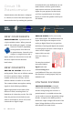
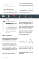
NEW IDEAS
POTENTIOMETERS are not polarized
and can be installed in either direction.
Note that swapping the 5V and GND pins
will reverse its behavior.
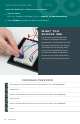
FLAT EDGE