
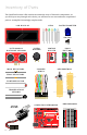
Data Sheet

18 : circuit 1a
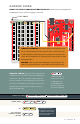
ONBOARD LED PIN 13:
You may have noticed a second,
smaller LED blinking in unison
with the LED in your breadboard
circuit. is is known as the
onboard LED, and you can nd
one on almost any Arduino or
Arduino-compatible board. In
most cases, this LED is connected
to digital pin 13 (D13), the
same pin used in this circuit.
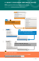
CODE TO NOTE
SETUP AND LOOP:
void setup(){} &
void loop(){}
Every Arduino program needs these two functions. Code that goes in
between the curly brackets {} of setup()runs once. e code in
between the loop()curly brackets {} runs over and over until the
RedBoard is reset or powered o.
INPUT OR OUTPUT?:
pinMode(13, OUTPUT);
Before you can use one of the digital pins, you need to tell the RedBoard
whether it is an INPUT or OUTPUT. We use a built-in “function” called
pinMode() to make pin 13 a digital output. You’ll learn more about
digital inputs in Project 2.
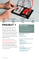
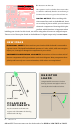
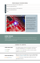
PROGRAM OVERVIEW
Turn the LED on by sending power (5V) to digital pin 13.
Wait 2 seconds (2000 milliseconds).
Turn the LED off by cutting power (0V) to digital pin 13.
Wait 2 seconds (2000 milliseconds).
Repeat.
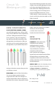
NEW IDEAS
CODE TO NOTE: e sketches that accompany each circuit introduce new programming techniques and
concepts as you progress through the guide. e Code to Note section highlights specic lines of code from the
sketch and explains them in greater detail.