
Data Sheet

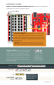

IOREF
RESET
RESET
7-15V
SCL
SDA
AREF
GND
13
12
~11
~10
~9
8
7
~6
~5
4
~3
2
1
0
TX
RX
13
3.3V
5V
GND
GND
VIN
A0
A1
A2
A3
A4
A5
POWER ANALOG IN
DIGITAL (PWM~)
ON
ISP
TX
RX
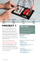
START SOMETHING
+ –
+ –
+ –
+ –
1
2
3
4
5
6
7
8
9
10
11
12
13
14
15
16
17
18
19
20
21
22
23
24
25
26
27
28
29
30
1
2
3
4
5
6
7
8
9
10
11
12
13
14
15
16
17
18
19
20
21
22
23
24
25
26
27
28
29
30
abcde fghij
abcde fghij
+ - + -
+ - + -
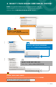
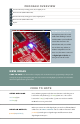
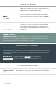
HOOKUP GUIDE
READY TO START HOOKING EVERYTHING UP? Check out the circuit diagram and
hookup table below to see how everything is connected.
10k
100k
330
16 : circuit 1a
CONNECTION TYPES
REDBOARD CONNECTION
BREADBOARD CONNECTION
JUMPER WIRES
D13
to
J2
GND
to
E1
LED
A1(-)
to
A2(+)
330Ω RESISTOR
(ORANGE, ORANGE,
BROWN)
E2
to
F2
D13
to
J2
In this table, a yellow
highlight indicates that a
component has polarity
and will only function if
properly oriented.
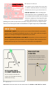
CIRCUIT DIAGRAMS: Each circuit contains a circuit diagram, which
acts as a visual aid designed to make it easier for you to see how your circuit
should be built. Each colored line represents a jumper wire connection in the
circuit. All wires should have two connection points, which you also see in the
hookup table below.
COLORS: Please note that while traditionally red is used for power and
black is used for ground, all wires, no matter their color, function the same.
HOOKUP TABLES: Many electronics beginners nd
it helpful to have a coordinate system when building their
circuits. For each circuit, you’ll nd a hookup table that
lists the coordinates of each component or wire and where
it connects to the RedBoard, the breadboard, or both. e
breadboard has a letter/number coordinate system, just
like the game Battleship.
…means one end of a
component connects
to digital pin 13 on
your RedBoard and
the other connects to
J2 on the breadboard
FLAT EDGE