
Data Sheet

15 : circuit 1a
R = Resistance in ohms (Ω)
is equation is used to calculate what resistor values
are suitable to suciently limit the current owing to
the LED so that it does not get too hot and burn out.
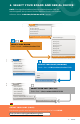
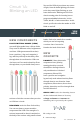
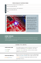
DIGITAL OUTPUT: When working with
microcontrollers such as the RedBoard, there
are a variety of pins to which you can connect
electronic components. Knowing which pins
perform which functions is important when
building your circuit. In this circuit, we will be using what is known as a digital output.
There are 14 of these pins found on the RedBoard. A digital output only has two states:
ON or OFF. These two states can also be thought of as HIGH or LOW, TRUE or FALSE.
When an LED is connected to one of these pins, the pin can only perform two jobs: turning
on the LED and turning off the LED. We’ll explore the other pins and their functions in
later circuits.
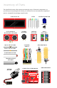
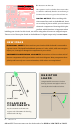
POLARIZED
COMPONENTS
Pay close attention to the LED. e
negative side of the LED is the short leg,
marked with a at edge.
FLAT EDGE
SHORT LEG
–
+
RESISTOR
LEADS
Components like resistors need to have
their legs bent into 90° angles in order to
correctly t in the breadboard sockets.
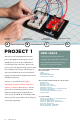
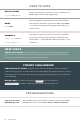
NEW IDEAS
ELECTRICAL SAFETY: Never work on your circuits while the board is connected to
a power source. The SparkFun RedBoard operates at 5 volts, which, while not enough to
injure you, is enough to damage the components in your circuit.
COMPONENT ORIENTATION & POLARITY: Instructions on how to orient each of
the new components will be given before each circuit diagram. Many components have
polarity and have only one correct orientation, while others are nonpolarized.
IOREF
RESET
RESET
7-15V
SCL
SDA
AREF
GND
13
12
~11
~10
~9
8
7
~6
~5
4
~3
2
1
0
TX
RX
13
3.3V
5V
GND
GND
VIN
A0
A1
A2
A3
A4
A5
POWER ANALOG IN
DIGITAL (PWM~)
ON
ISP
TX
RX
START SOMETHING