SparkFun Inventor ’s Kit VERSION 4.
SparkFun Inventor’s Kit, Version 4.0 WELCOME TO THE SPARKFUN INVENTOR’S KIT (SIK) GUIDE. This is your map for navigating beginning embedded electronics. This booklet contains all the information you will need to build five projects encompassing the 16 circuits of the SIK for the SparkFun RedBoard. At the center of this manual is one core philosophy: that anyone can (and should) play around with electronics.
Contents INTRODUCTION 2 2 The RedBoard Platform 3 Baseplate Assembly 4 RedBoard Anatomy 5 Breadboard Anatomy 6 The Arduino IDE 10 Inventory of Parts PROJECT 1: LIGHT 12 13 Circuit 1A: Blinking an LED 20 Circuit 1B: Potentiometer 26 Circuit 1C: Photoresistor 31 Circuit 1D: RGB Night-Light PROJECT 2: SOUND 36 37 Circuit 2A: Buzzer 42 Circuit 2B: Digital Trumpet 47 Circuit 2C: “Simon Says” Game PROJECT 3: MOTION 53 54 Circuit 3A: Servo Motors 60 Circuit 3B: Distance Sensor 65 Circuit 3C: Motion Alar
The RedBoard Platform THE DIY REVOLUTION: At SparkFun we believe that an understanding of electronics is a core literacy that opens up a world of opportunities in the fields of robotics, Internet of Things (IoT), engineering, fashion, medical industries, environmental sciences, performing arts and more. This guide is designed to explore the connection between software and hardware, introducing Arduino code and SparkFun parts as they are used in the context of building engaging projects.
Baseplate Assembly Before you can build circuits, you’ll want to first assemble the breadboard baseplate. This apparatus makes circuit building easier by keeping the RedBoard microcontroller and the breadboard connected without the worry of disconnecting or damaging your circuit. TO BEGIN, collect your parts: the RedBoard, breadboard, included screwdriver, baseplate and two baseplate screws. Your screwdriver has both Phillips and flatheads.
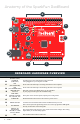
Anatomy of the SparkFun RedBoard F E B D 7 ~6 ~5 4 ~3 2 TX 1 RX 0 RESET SCL SDA AREF GND 13 12 ~11 ~10 ~9 8 H DIGITAL (PWM~) 13 TX RX ON START SOMETHING C G I K A5 A4 A3 A2 A1 ANALOG IN A0 VIN GND GND POWER 5V 3.3V IOREF 7-15V A RESET ISP J REDBOARD HARDWARE OVERVIEW A POWER IN (BARREL JACK) B POWER IN (USB PORT) C LED (RX: RECEIVING) Shows when the FTDI chip is receiving data bits from the computer.
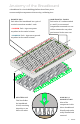
Anatomy of the Breadboard A breadboard is a circuit-building platform that allows you to connect multiple components without using a soldering iron. POWER BUS H O R I Z O N TA L R O W S Each side of the breadboard has a pair of Each series of 5 sockets marked vertical connections marked – and + a–e and f–j are connected. + POWER: Each + sign runs power anywhere in the vertical column. Components connected to a row will be connected to any other part inserted in the same row.
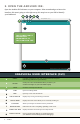
The Arduino IDE IN ORDER TO GET YOUR REDBOARD UP AND RUNNING, you'll need to download the newest version of the Arduino software from www.arduino.cc (it's free!). This software, known as the Arduino IDE (Integrated Development Environment), will allow you to program the RedBoard to do exactly what you want. It’s like a word processor for coding. With an internet-capable computer, open up your favorite browser and type the following URL into the address bar: DOWNLOAD THE SOFTWARE HERE: arduino.
4. DOWNLOAD AND INSTALL THE SIK CODE Each of the circuits you will build in the SparkFun Inventor’s Kit has an Arduino code sketch already written for it. This guide will show you how to manipulate that code to control your hardware. DOWNLOAD THE CODE HERE: sparkfun.com/SIKcode COPY “SIK GUIDE CODE” INTO “EXAMPLES” LIBRARY IN ARDUINO FOLDER Your browser will download the code automatically or ask you if you would like to download the .zip file. Select “Save File.
5. OPEN THE ARDUINO IDE: Open the Arduino IDE software on your computer. Poke around and get to know the interface. We aren’t going to code right away; this step is to set your IDE to identify your RedBoard. E B D C G Blink | Arduino 1.8.5 A K Blink H THE THREE MOST I M P O R TA N T COMMANDS IN THE ARDUINO IDE I F Arduino/Genuino Uno on/dev/cu.usbserialDNO18JWS GRAPHICAL USER INTERFACE (GUI) A VERIFY Compiles and approves your code.
IK_Circuit_1A-Blink IK_Circuit_1A-Potentiometer IK_Circuit_1A-Photoresistor IK_Circuit_1A-RGBNightlight IK_Circuit_1A-Buzzer IK_Circuit_1A-DigitalTrumpet NOTE: Your SparkFun RedBoard and the Arduino/Genuino UNO are IK_Circuit_1A-SimonSays File 6. SELECT YOUR BOARD AND SERIAL DEVICE interchangeable, but you won’t find the RedBoard listed in the Arduino software. Select “ARDUINO/GENUINO UNO” instead.
Inventory of Parts The SparkFun Inventor’s Kit contains an extensive array of electronic components. As you work your way through each circuit, you will learn to use new and more complicated parts to accomplish increasingly complex tasks.
Let’s Get Started With Your First Circuit! 11 : intro
BLINKING AN LED A READING A POTENTIOMETER READING A PHOTORESISTOR B C RGB NIGHT-LIGHT D PROJECT 1 NEW IDEAS Welcome to your first SparkFun Inventor’s Kit Each project will introduce new project. Each project is broken up into several concepts and components, which will circuits, the last circuit being a culmination of be described in more detail as you the technologies that came before. There are five progress through the circuits.
Circuit 1A: Blinking an LED You can find LEDs in just about any source of light, from the bulbs lighting your home to the tiny status lights flashing on your home electronics. Blinking an LED is the classic starting point for learning how to program embedded electronics. It’s the “Hello, World!” of microcontrollers. In this circuit, you’ll write code that makes an LED blink on and off. LED 330Ω NEW COMPONENTS which you can look up using are small lights made from a silicon diode.
RESET 7 ~6 ~5 4 ~3 2 TX 1 RX 0 SCL SDA AREF GND 13 12 ~11 ~10 ~9 8 R = Resistance in ohms (Ω) DIGITAL (PWM~) 13 TX RX This equation is used to calculate what resistor values are suitable to sufficiently limit the current flowing to ON the LED so that it does not get too hot and burn out. START SOMETHING ISP DIGITAL OUTPUT: When working with A5 A4 A3 A2 A1 ANALOG IN A0 VIN GND GND 5V 3.
HOOKUP GUIDE READY TO START HOOKING EVERYTHING UP? Check out the circuit diagram and hookup table below to see how everything is connected. F L AT E D G E e f g h i j 1 2 3 3 4 4 5 5 6 6 7 7 8 8 9 9 ++ -– 7-15V 3.
Open the Arduino IDE Connect the RedBoard to a USB port on your computer. Open the Sketch: File > Examples > SIK_Guide_Code-V_4 > CIRCUIT_1A-BLINK Select UPLOAD to program the sketch on the RedBoard. Arduino Tools Help File Edit Sketch New Open Open Recent Sketchbook Examples Close Save Save As Page Setup Print Tools Help 01.Basics 02.Digital 03.Analog 04.Communication 05.Control 06.Sensors 07.Display 08.Strings 09.USB 10.
PROGRAM OVERVIEW 1 Turn the LED on by sending power (5V) to digital pin 13. 2 Wait 2 seconds (2000 milliseconds). 3 Turn the LED off by cutting power (0V) to digital pin 13. 4 Wait 2 seconds (2000 milliseconds). 5 Repeat. ONBOARD LED PIN 13: You may have noticed a second, smaller LED blinking in unison with the LED in your breadboard circuit. This is known as the onboard LED, and you can find one on almost any Arduino or Arduino-compatible board.
CODE TO NOTE DIGITAL OUTPUT: When you’re using a pin as an OUTPUT, you can command it to be digitalWrite(D13, HIGH); HIGH (output 5 volts) or LOW (output 0 volts). Causes the program to wait on this line of code for the amount of DELAY: time in between the brackets, represented in milliseconds (2000ms delay(2000); = 2s). After the time has passed, the program will continue to the next line of code.
TROUBLESHOOTING I still get an error when uploading my code If you’re sure you have the correct Board selected but you still can’t upload, check that you have selected the correct serial port. You can change this in Tools > Serial Port > your_serial_port. Depending on how many devices you have plugged into your computer, you may have several active serial ports. Make sure you are selecting the Which serial port is correct one.
Circuit 1B: Potentiometer of the knob with your RedBoard, you can make volume controls, speed controls, angle sensors and a ton of other useful inputs for your projects. In this circuit, Potentiometers (also known as “trimpots” or “knobs”) are one of the basic inputs for electronic devices. By tracking the position LED blinks. POTENTIOMETER NEW COMPONENTS 7 JUMPER WIRES RESISTOR ANALOG INPUTS: So far, we’ve only dealt with outputs. The RedBoard also has POTENTIOMETER: A potentiometer is inputs.
HOOKUP GUIDE READY TO START HOOKING EVERYTHING UP? Check out the circuit diagram and hookup table below to see how everything is connected. F L AT E D G E e f g h i j 1 2 3 3 4 4 5 5 6 6 7 7 8 8 9 9 ++ -– 7-15V 10k d 100k c 330 b 2 RESET 12 3.
Open the Arduino IDE Connect the RedBoard to a USB port on your computer. Open the Sketch: File > File > Examples > SIK_Guide_Code-V_4 > CIRCUIT_1B-POTENTIOMETER Select UPLOAD to program the sketch on the RedBoard. W H AT Y O U SHOULD SEE You should see the LED blink faster or slower in accordance with your potentiometer. The delay between each flash will change based on the position of the knob.
ARDUINO PRO TIP ARDUINO SERIAL MONITOR: The Blink | Arduino 1.8.5 Serial Monitor is one of the Arduino IDE’s many great included features. When Serial Monitor Blink working with embedded systems, it helps to see and understand the values that your program is trying to work with, and it can be a powerful debugging tool when you run into issues where your code is not behaving the way you expected it to. This Arduino/Genuino Uno on/dev/cu.
CODE TO NOTE Serial commands can be used to send and receive data from your computer. This line of code tells the RedBoard that we SERIAL BEGIN: want to “begin” that communication with the computer, the Serial.begin(9600); that the baud rate, 9600, is the same as the one we selected same way we would say “Hi” to initiate a conversation. Notice in the monitor. This is the speed at which the two devices communicate, and it must match on both sides.
TROUBLESHOOTING The potentiometer always reads as 0 or 1023 Make sure that your 5V, A0 and GND pins are properly connected to the three pins on your potentiometer. It is easy to misalign a wire with the actual pot pin. Make sure that you have selected the correct baud rate, No values or random 9600. Also ensure that you are on the correct serial characters in port.
Circuit 1C: Photoresistor circuit, you’ll be using a photoresistor, which changes resistance based on how much light the sensor receives. Using this sensor you can make a simple night-light In circuit 1B, you got to use a potentiometer, which varies resistance that turns on when the room gets dark based on the twisting of a knob. In this and turns off when it is bright.
HOOKUP GUIDE READY TO START HOOKING EVERYTHING UP? Check out the circuit diagram and hookup table below to see how everything is connected. F L AT E D G E e f g h i ++ -– j 1 2 3 3 4 4 5 5 6 6 7 7 8 8 9 9 7-15V 10k d 100k c 330 b 2 RESET 12 3.
Open the Arduino IDE Connect the RedBoard to a USB port on your computer. Open the Sketch: File > Examples > SIK_Guide_Code-V_4 > CIRCUIT_1C-PHOTORESISTOR Select UPLOAD to program the sketch on the RedBoard. W H AT Y O U SHOULD SEE The program stores the light level in a variable. Using an if/else statement, the variable value is compared to the threshold. If the variable is above the threshold (it’s bright), turn the LED off. If the variable is below the threshold (it’s dark), turn the LED on.
CODE TO NOTE IF ELSE STATEMENTS: The if else statement lets your code react to the world by if(logic statement){ running one set of code when the logic statement in the //run if true round brackets is true and another set of code when the } logic statement is false. For example, this sketch uses an else{ if statement to turn the LED on when it is dark, and else //run if false statement to turn the LED off when it is light.
TROUBLESHOOTING Nothing is printing in the Serial Monitor Try unplugging your USB cable and plugging it back in. In the Arduino IDE, go to Tools > Port, and make sure that you select the right port. Start the Serial Monitor in Arduino. Look at the value that the photoresistor is reading in a bright room (e.g., 915). Cover the The light never turns on or always stays on photoresistor, or turn the lights off. Then look at the new value that the photoresistor is reading (e.g., 550).
Circuit 1D: RGB Night-Light In this circuit, you’ll take the night-light concept to the next level by adding an RGB LED, which is three differently colored Light-Emitting Diodes (LEDs) built into one component. RGB stands for Red, Green and Blue, and these three colors can be combined to create any color of the rainbow! 3 330Ω PHOTORESISTOR 12 JUMPER WIRES RESISTORS 10KΩ YOU NEED RESISTOR POTENTIOMETER blue — inside a normal LED housing.
HOOKUP GUIDE READY TO START HOOKING EVERYTHING UP? Check out the circuit diagram and hookup table below to see how everything is connected. F L AT E D G E b c d e f g h i ++ -– j 1 2 2 330 3 3 330 4 4 5 5 6 6 7 7 8 8 9 9 7-15V 100k 330 100k 10k 100k 10k 10 11 11 RESET 12 12 3.
Open the Arduino IDE Connect the RedBoard to a USB port on your computer. Open the Sketch: File > Examples > SIK_Guide_Code-V_4 > SIK_CIRCUIT_1D-RGB NIGHT LIGHT Select UPLOAD to program the sketch on the RedBoard. W H AT Y O U SHOULD SEE This sketch is not dissimilar from the last. It reads the value from the photoresistor, compares it to a threshold value, and turns the RGB LED on or off accordingly. This time, however, we’ve added a potentiometer back into the circuit.
CODE TO NOTE The analogWrite() function outputs a voltage between ANALOG OUTPUT (PWM): analogWrite(RedPin, 100); 0 and 5V on a pin. The function breaks the range between 0 and 5V into 255 little steps. Note that we are not turning the LED on to full brightness (255) in this code so that the night-light is not too bright. Feel free to change these values and see what happens.
CODING CHALLENGES ADD MORE COLORS: You can create many more colors with the RGB LED. Use the analogWrite() function to blend different values of red, green and blue together to make even more colors. You can divide the potentiometer value and make more nested if statements so that you can have more colors as you twist the knob. MULTI-COLOR BLINK: Try using delays and multiple color functions to have your RGB LED change between multiple colors when it is dark.
BUZZER D I G I TA L T R U M P E T A ‘ S I M O N S AY S ’ G A M E B C PROJECT 2 In Project 2, you will venture into the world of buttons and buzzers while building your own “Simon Says” game! “Simon Says” is a game in which the LEDs flash a pattern of red, green, yellow and blue blinks, and the user must recreate the pattern using color-coded buttons before the timer runs out.
Circuit 2A: Buzzer In this circuit, you’ll use the RedBoard and a small buzzer to make music, and you’ll learn how to program your own songs using arrays. POTENTIOMETER NEW COMPONENTS BUZZER: The buzzer uses a small PIEZO BUZZER 4 JUMPER WIRES YOU NEED frequency on the specified pin. The frequency and duration can both be passed to the tone() function when calling it. magnetic coil to vibrate a metal disc inside a plastic housing.
HOOKUP GUIDE READY TO START HOOKING EVERYTHING UP? Check out the circuit diagram and hookup table below to see how everything is connected. a b c d e f g h i ++ -– j 1 1 2 2 3 3 4 4 5 5 6 6 7 7 8 8 9 9 RESET ++ -– 7-15V RESET 12 3.3V 13 13 5V 14 14 15 15 16 16 17 17 18 18 19 19 A2 20 20 A3 21 21 A4 22 22 A5 23 23 24 24 25 25 26 26 27 27 28 28 potentiometer’s legs are used in these circuits.
Open the Arduino IDE Connect the RedBoard to a USB port on your computer. Open the Sketch: File > Examples > SIK_Guide_Code-V_4 > SIK_CIRCUIT_2A-BUZZER Select UPLOAD to program the sketch on the RedBoard. W H AT Y O U SHOULD SEE When the program begins, a song will play from the buzzer once. To replay the song, press the reset button on the RedBoard. Use the potentiometer to adjust the volume. PROGRAM OVERVIEW Play the first note for x number of beats using the play() function.
CODE TO NOTE The char, or character, variable stores character values. For example, in this sketch, the play() function gets passed two variables: a character CHARACTER VARIABLES: void play(char note, int beats) variable that represents the mucial note we want to play and an integer variable that represents how long to play that note. A second array takes the character variable and associates a frequency value to it.
TROUBLESHOOTING The song is too quiet or too loud Turn the potentiometer to adjust the volume. Try pressing the reset button on the RedBoard. If that No sound is playing doesn’t work, check your wiring of the buzzer. It’s easy to misalign a pin with a jumper wire or reverse the buzzer. You’ve completed Circuit 2A! Continue to circuit 2B to explore digital inputs and buttons.
Circuit 2B: Digital Trumpet Learn about digital inputs and buttons as you build your own digital trumpet! Buttons are all around us, from the keys on your keyboard to the buttons on your remote control. YOU NEED POTENTIOMETER PIEZO BUZZER NEW COMPONENTS BUTTONS: Also known as momentary switches, buttons only remain in their ON state as long as they’re being actuated, or pressed. Most often momentary switches are 10 JUMPER WIRES 3 PUSH BUTTONS of as ON or OFF, TRUE or FALSE, HIGH or LOW.
HOOKUP GUIDE READY TO START HOOKING EVERYTHING UP? Check out the circuit diagram and hookup table below to see how everything is connected. b c d e f g h i ++ -– j 1 2 2 3 3 4 4 5 5 6 6 7 7 8 8 9 9 7-15V RESET 12 3.
Open the Arduino IDE Connect the RedBoard to a USB port on your computer. Open the Sketch: File > Examples > SIK_Guide_Code-V_4 > SIK_CIRCUIT_2B-DIGITAL TRUMPET Select UPLOAD to program the sketch on the RedBoard. W H AT Y O U SHOULD SEE Different tones will play when you press different keys. Turning the potentiometer will adjust the volume. PROGRAM OVERVIEW Check to see if the first button is pressed. 1 A: If it is, play the frequency for c. B: If it isn’t, skip to the next else if statement.
CODE TO NOTE To declare a standard input, use the line INTERNAL PULL-UP RESISTOR: pinMode(pin, INPUT );. If you would like to use one of the RedBoard’s built-in pull-up 20kΩ resistors, it would look like this: pinMode(pin, INPUT_ PULLUP); pinMode(pin, INPUT_PULLUP);. The advantage of external pull-ups is being able to choose a more exact value for the resistor. DIGITAL INPUT: Check to see if an input pin is reading HIGH digitalRead(pin); depending on the reading. (5V) or LOW (0V).
TROUBLESHOOTING The buzzer is too loud or too quiet The RedBoard thinks one key is always pressed Turn the potentiometer to adjust the volume. Check your wiring. You may have GND and 5V backward if one or more buttons behave as though they’re pressed all the time. First, make sure that the wiring is correct. It is easy to misalign The buttons are a wire with a button leg.
pattern, which the player must remember 100k The “Simon Says” game uses LEDs to flash a 330 Circuit 2C: “Simon Says” Game and repeat using four buttons. This simple electronic game has been a classic since the late 1970s. Now you can build your own! 4 LEDS POTENTIOMETER PIEZO BUZZER 16 JUMPER WIRES 4 PUSH BUTTONS 4 330Ω NEW CONCEPTS FOR LOOPS: A for loop repeats a YOU NEED RESISTORS brackets, which prints the value of i to the Serial Monitor. section of code a set number of times.
HOOKUP GUIDE READY TO START HOOKING EVERYTHING UP? Check out the circuit diagram and hookup table below to see how everything is connected. a b c d e f g h i 1 2 2 3 4 3 5 6 6 100k 7 8 8 330 9 9 10k 13 100k 3.
Open the Arduino IDE Connect the RedBoard to a USB port on your computer. Open the Sketch: File > Examples > SIK_Guide_Code-V_4 > SIK_CIRCUIT_2C-SIMON SAYS Select UPLOAD to program the sketch on the RedBoard. W H AT Y O U SHOULD SEE The circuit will flash all of the LEDs and play a melody. After a few seconds, it will flash the first light in the pattern.
Start a timer, and wait for the player to press a button. The player has 1.5 seconds to press the correct button. A: If the time limit runs out before a button is pressed, the player loses. 4 B: If the player presses the wrong button, the player loses. C: If the player presses the right button, move on to the next number in the sequence. D: Repeat this process until the player has lost or correctly repeated the sequence for this round.
FUNCTIONS TO NOTE allLEDoff(); buttonCheck(); Turns all four LEDs off. Uses digitalRead() to check which button is pressed. Returns 0, 1, 2 or 3 if one of the buttons is pressed. Returns 4 if no button is pressed. Flashes the LEDs and plays tones in a sequence. Resets the round startSequence(); counter and generates a new random sequence for the user to remember. winSequence(); loseSequence(); Plays a sequence of tones, turns all of the LEDs on, and then waits for the player to press a button.
TROUBLESHOOTING One of the LEDs isn’t lighting up The buzzer is too loud or too quiet Make sure your LED is oriented in the right direction. If the LED still doesn’t work, try wiggling the resistor and the wires that connect to the LED. Turn the potentiometer to adjust the volume. Carefully check your wiring for each button. One leg of the One of the buttons isn’t button should connect to a pin on the RedBoard; the other leg working should connect to the ground rail on the breadboard.
SERVO MOTORS D I S TA N C E S E N S O R A B MOTION ALARM C PROJECT 3 Tired of your cat walking all over the kitchen counter? How about the dog getting into the garbage? Need a way to stop your younger sibling from sneaking into your bedroom? Learn how to protect against all of these annoyances as you build a multipurpose motion alarm. The alarm detects distance and motion using an ultrasonic distance sensor, and creates motion using a servo motor.
Circuit 3A: Servo Motors In this circuit, you will learn how to wire a servo and control it with code. Servo motors can be told to move to a specific position and stay there. Low-cost servo motors were originally used to steer RC airplanes and cars, but they have become popular for any project where precise movement is needed. YOU NEED POTENTIOMETER SERVO 8 JUMPER WIRES SCISSORS (NOT INCLUDED) NEW COMPONENTS SERVO MOTORS: Regular DC motors have two wires.
ARDUINO LIBRARIES: Writing code creating a servo object, like this: that sends precise PWM signals to the Servo myServo; servo would be time consuming and would require a lot more knowledge about the servo. Luckily, the Arduino IDE has hundreds of built-in and user-submitted containers of code called libraries. One of Objects look a lot like variables, but they can do much more. Objects can store values, and they can have their own functions, which are called methods.
HOOKUP GUIDE READY TO START HOOKING EVERYTHING UP? Check out the circuit diagram and hookup table below to see how everything is connected. b c d e f g h i ++ -– j 1 2 2 3 3 4 4 5 5 6 6 7 7 8 8 9 9 7-15V RESET 12 3.
Open the Arduino IDE Connect the RedBoard to a USB port on your computer. Open the Sketch: File > Examples >SIK_Guide_Code-V_4 > SIK_CIRCUIT_3A-SERVO Select UPLOAD to program the sketch on the RedBoard. W H AT Y O U SHOULD SEE Turning the potentiometer will cause the servo arm to turn. The servo will mimic the movement of the potentiometer, twisting in the same clockwise or counterclockwise direction. If you’ve attached a servo mount to the arm as shown, this movement will be easier to see.
CODE TO NOTE The .attach(); method tells the servo object to which pin the signal wire is SERVO ATTACH: attached. It will send position signals myServo.attach(9); to this pin. In this sketch, pin 9 is used. Remember to only use digital pins that are capable of PWM. As shown in previous circuits, the analog pin values on your microcontroller vary from 0 to 1023.
TROUBLESHOOTING The servo doesn’t move Check the wiring on your servo. Make sure the red wire on the servo cord is connected to 5V, the black wire is connected to GND and the white signal wire is connected to digital pin 9. Although these servos are supposed to move from 0 to 180 The servo is twitching degrees, sometimes sending them to the extremes of their range causes them to twitch (the servo is trying to move farther than it can).
Circuit 3B: Distance Sensor Distance sensors are amazing tools with all kinds of uses. They can sense the presence of an object, they can be used 10k 100k 330 in experiments to calculate speed and acceleration, and they can be used in robotics to avoid obstacles.
HOOKUP GUIDE READY TO START HOOKING EVERYTHING UP? Check out the circuit diagram and hookup table below to see how everything is connected.
Open the Arduino IDE Connect the RedBoard to a USB port on your computer. Open the Sketch: File > Examples > SIK_Guide_Code-V_4 > CIRCUIT_3B-DISTANCE SENSOR Select UPLOAD to program the sketch on the RedBoard. W H AT Y O U SHOULD SEE Move your hand or a large, flat object closer and farther away from the distance sensor. As the object approaches, the light will change from green to yellow to red. Open the Arduino Serial Monitor to see the distance being read from the sensor.
CODE TO NOTE The float variable, short for floating-point number, is similar to an integer except it can FLOAT VARIABLES: float echoTime; represent numbers that contain a decimal point. Floats are good for representing values that need to be more precise than an integer. Floats allow us to measure precise distances such as 9.33 inches instead of just 9 inches.
TROUBLESHOOTING The RGB LED colors aren’t working or a color is missing Check the connection for the wire and resistor connected to each leg of the LED. Ensure the RGB LED is inserted in the correct orientation. Open up the Serial Monitor on your computer. You The distance sensor doesn’t should see a stream of distances being printed in the seem to work monitor. If they are all reading 0 or jumping around, then check the wiring on your sensor.
Circuit 3C: Motion Alarm Time to take your distance sensor project to the next level. Let’s imagine you want to stop your cat from prowling around your countertop. This circuit uses light, sound and motion to scare away your cat when it is detected by the distance sensor. Using a servo motor, you can add a moving pop-up to animate your alarm.
3. Attach the hook end of the linkage rod to the end hole on your servo mount. The motor should be reattached to the baseplate with Dual Lock. 4. Cut out the pop-up image of your choice. We chose this public domain menacing cat image (http://sfe.io/cat). The image you choose should be about 2.5 inches x 2.5 inches and can be drawn or printed. Leave a rectangular strip of paper under the image that is about 2 inches long. 5. Fold along the bottom of the image.
HOOKUP GUIDE READY TO START HOOKING EVERYTHING UP? Check out the circuit diagram and hookup table below to see how everything is connected.
Open the Arduino IDE Connect the RedBoard to a USB port on your computer. Open the Sketch: File > Examples > SIK_Guide_Code-V_4 > SIK_CIRCUIT_3C-MOTION ALARM Select Upload to program the sketch on the RedBoard. W H AT Y O U SHOULD SEE The RGB LED will behave as in your last circuit. It will be green when objects are far, yellow when they are midrange and red when they are close. When an object is close, the buzzer will also beep, and the servo will rotate back and forth.
CODE TO NOTE In circuit 2A, you made songs using a buzzer and the tone() function, but you gave the function three parameters: a pin NO TONE number, a frequency and a duration. You can leave out the third FUNCTION: noTone(pin_number); parameter, and the tone will play until you change it or turn it off. noTone() turns off a pin that has been activated with the tone() command. CODING CHALLENGES CHANGE THE SERVO BEHAVIOR: Try changing the way your servo behaves when the distance sensor is triggered.
TROUBLESHOOTING Make sure all of your servo wires are connected. Be sure that the black wire is connected to the negative The servo doesn’t work rail and the red wire is connected to the positive rail. Make sure you are using a digital pin that is capable of PWM. The two lines of code that pass angles to the servo The pop-up is moving too much motor are myservo.write(45); and myservo. or not enough write(135);. Try changing these angle values to fine-tune your mechanism.
LCD “HELLO, WORLD!” T E M P E R AT U R E S E N S O R A “DIY WHO AM I?” GAME B C PROJECT 4 Printing data to the Arduino Serial Monitor is a great way to see data from the RedBoard. But, what if you want to make your project mobile and see sensor values away from your computer? This project will show you how to do exactly that. You’ll learn about Liquid Crystal Displays (LCDs) and how to print things like sensor data and strings of words to the display.
Circuit 4A: LCD “Hello, World!” Printing “Hello, world!” is usually the first thing that programming tutorials will have you do in a new language. This guide starts by blinking an LED, but now we’re going to print out real text using a Liquid Crystal Display (LCD). YOU NEED LCD DISPLAY POTENTIOMETER NEW COMPONENTS CHARACTER LIQUID CRYSTAL DISPLAY (LCD): Designed to show a grid of letters, numbers and other special characters, LCDs are great for printing data and showing values.
HOOKUP GUIDE READY TO START HOOKING EVERYTHING UP? Check out the circuit diagram and hookup table below to see how everything is connected. b c d e f g h i ++ -– j 1 2 2 3 3 4 4 5 5 6 6 7 7 8 8 9 9 7-15V RESET 12 3.
Open the Arduino IDE Connect the RedBoard to a USB port on your computer. Open the Sketch: File > Examples > SIK_Guide_Code-V_4 > CIRCUIT_4A-LCD HELLO WORLD Select UPLOAD to program the sketch on the RedBoard. W H AT Y O U SHOULD SEE The LCD screen will show “Hello, world!” and on the row below a counter will count every second that passes. Adjusting the potentiometer will change the contrast on the LCD screen. PROGRAM OVERVIEW 1 Import the LCD library.
CODE TO NOTE LCD LIBRARY: Includes the LiquidCrystal library in your #include program. As with servos, you need to create an LCD LCD LIBRARY INSTANCE: object and give it a name (you can make LiquidCrystal LCD_name(RS_pin, enable_pin, d4, d5, d6, d7); more than one). The numbers in the brackets are pins on the RedBoard that connect to specific pins on the LCD. This line initializes the LCD object and tells LCD BEGIN: the program the LCD’s dimensions. In this lcd.
TROUBLESHOOTING Adjust the contrast by twisting the potentiometer. Try both The screen is blank or directions until you see characters display. Do not twist flickering the potentiometer past its stopping points. Also, check the potentiometer, and make sure it's wired correctly. Not working at all Double check the circuit’s wiring. There are a lot of wires in this circuit, and it’s easy to mix up one or two.
Circuit 4B: Temperature Sensor Want to create a DIY environmental monitor or weather station? You can use a small, low-cost sensor like the TMP36 to make devices that track and respond to temperature. In this activity you will also use the LCD screen to display sensor readings, a common use for LCDs in electronics projects. TMP LCD DISPLAY POTENTIOMETER TEMPERATURE SENSOR NEW COMPONENTS TMP36 TEMPERATURE SENSOR: This temperature sensor has three legs.
HOOKUP GUIDE READY TO START HOOKING EVERYTHING UP? Check out the circuit diagram and hookup table below to see how everything is connected. TMP b c d e f g h i j 1 2 2 3 3 4 4 5 5 6 6 7 7 8 8 9 9 ++ -– 7-15V RESET 12 3.
Open the Arduino IDE Connect the RedBoard to a USB port on your computer. Open the Sketch: File > Examples > SIK_Guide_Code-V_4 > SIK_CIRCUIT_4B-TEMPERATURE SENSOR Select UPLOAD to program the sketch on the RedBoard. W H AT Y O U SHOULD SEE The LCD will show the temperature in Celsius and Fahrenheit. The temperature readings will update every second. An easy way to see the temperature change is to press your finger to the sensor.
CODE TO NOTE Many of the sensors that you will use with your microcontroller work by changing a voltage in some predictable way in response to a property of the world (like temperature, light or magnetic fields). VOLTAGE CONVERSION ALGORITHMS Often, you will need to build an algorithm that converts these voltages to the desired value and units. The temperature sensor is a great example of this code. We use three equations to convert a voltage value into degrees in C and F. voltage = analogRead(A0) * 0.
TROUBLESHOOTING Make sure that you wired the temperature sensor correctly. Sensor is The temperature sensor can get warm to the touch if it is wired heating up incorrectly. Disconnect power from your microcontroller, rewire the circuit, and connect it back to your computer. Temperature Try pinching the sensor with your fingers to heat it up or pressing value is a bag of ice against it to cool it down. Also, make sure that the unchanging wires are connected properly to the temperature sensor.
Circuit 4C: “DIY Who Am I?” Game “DIY Who Am I?” is based on the popular Hedbanz game or HeadsUp! app. It’s a fun party game in which a player holds an LCD screen to his/her forehead, and other players give hints to help the player with the LCD guess the word on the screen.
POINTERS: As an advanced programming topic, pointers can be difficult to understand at first. For now, think of pointers as a variable that “points” to the value contained in a certain address in memory. In this sketch, the char* variable points to arrayOfStrings address and returns the character values to create a list of strings. BATTERY HOLDER ASSEMBLY Batteries are polarized. They have a positive end and a negative end.
HOOKUP GUIDE READY TO START HOOKING EVERYTHING UP? Check out the circuit diagram and hookup table below to see how everything is connected. b c d e f g h i ++ -– j 1 2 2 3 3 4 4 5 5 6 6 7 7 8 8 9 9 7-15V RESET 12 3.
Open the Arduino IDE Connect the RedBoard to a USB port on your computer. Open the Sketch: File > Examples > SIK_Guide_Code-V_4 > SIK_CIRCUIT_4C-DIY WHO AM I Select UPLOAD to program the sketch on the RedBoard. W H AT Y O U SHOULD SEE The game begins with the category of words, then runs through a short countdown. When the first round starts, the word to be guessed is displayed at top left, and a countdown starts in the bottom right.
CODE TO NOTE ARRAY OF STRINGS: Makes an array of strings. The strings are stored const char* array_name [array_ length] = as constants, so they can’t be changed once the program starts. {“string1”, “string2”...}; ROUNDING FUNCTION: This math function rounds a number up or down to round(value_to_round); the nearest whole number. RANDOM FUNCTION: This function takes a set of numbers and generates random(min, max); a pseudo-random number from that set.
CODING CHALLENGES CHANGE THE TIME LIMIT: Changing the time limit variable will change the difficulty of the game. CHANGE THE WORDS IN THE WORD LIST: Try changing the categories and words. The number of words in your words array must match the value of the variable arraySize . CHANGE THE WINNING AND LOSING SONGS: By changing the tones in the winner() and gameover() functions you can change which song plays at the end of the game. TROUBLESHOOTING Adjust the contrast by twisting the potentiometer.
MOTOR BASICS R E M O T E- C O N T R O L L E D R O B O T AUTONOMOUS ROBOT A B C PROJECT 5 Ah, robots. One of the most iconic and exciting electronics applications. In this project, you will learn all about DC motors and motor drivers by building your own robot! You’ll first learn motor control basics. Then you’ll control a tethered robot by sending it commands over serial.
Circuit 5A: Motor Basics In this circuit, you will learn the basic concepts behind motor control. Motors require a lot of current, so you can’t drive them directly from a digital pin on the RedBoard. Instead, you’ll use what is known as a motor controller or motor driver board to power and spin the motor B11 B12 PWMB PWMA A12 A11 ST BY accordingly.
voltage on VIN will be about 4.6–5V. However, if you power the RedBoard through the barrel jack (highlighted in the picture), the VIN pin will reflect that voltage. For example, if you were to power the barrel jack with 9V, the voltage out on VIN would also be 9V. Notice that the voltage range listed on the RedBoard near the barrel jack is 7–15V. This means that the input voltage should always be at or above 7V or should be at 7 ~6 ~5 4 ~3 2 TX 1 RX 0 SCL SDA AREF GND 13 12 ~11 ~10 ~9 8 or below 15V.
Once you’re finished with this project, removing the motor driver from the breadboard can be difficult due to its numerous legs. To make this easier, use the included screwdriver as a lever to gently pry it out. Be careful not to bend the legs as you remove it. The motors are polarized. However, motors are unique in that they will still work when the two connections are reversed. They will just spin in the opposite direction when hooked up backward.
VM VCC GND A01 A02 B02 B01 GND VM PWMA VCC A12 GND A11 A01 ST BY A02 B11 B02 B12 B01 GND MOTOR DRIVER PWMB GND PIN LABEL FUNCTION POWER/INPUT/ OUTPUT VM Motor Voltage Power VCC Logic Voltage Power PWMA AIN2 AIN1 STBY BIN1 BIN2 PWMB GND NOTES This is where you provide power for the motors (2.2V to 13.5V) This is the voltage to power the chip and talk to the microcontroller (2.7V to 5.
HOOKUP GUIDE READY TO START HOOKING EVERYTHING UP? Check out the circuit diagram and hookup table below to see how everything is connected. a b c d e f g h i VM PWMA 1 2 VCC A12 2 3 GND A11 3 4 A01 ST BY 4 5 A02 B11 5 6 B02 B12 6 7 B01 PWMB 7 8 GND GND 8 MOTOR DRIVER 9 7-15V SCL SDA AREF GND 13 12 ~11 ~10 ~9 8 9 RESET 12 3.
Open the Arduino IDE Connect the RedBoard to a USB port on your computer. Open the Sketch: File > Examples > SIK_Guide_Code-V_4 > CIRCUIT_5A-MOTOR BASICS Select UPLOAD to program the sketch on the RedBoard. W H AT Y O U SHOULD SEE Flip the switch. The motor will spin at the speed set by the motor speed variable (default is 0). Open the Serial Monitor, type any number from 30 to 255 or -30 to -255 , and then press Enter. Changes in speed will be hard to notice. Send 0 to stop the motor.
CODING CHALLENGES MAKE THE SWITCH CHANGE DIRECTIONS: Change the code so that the position of the switch changes the direction of the motor instead YOU of turning it on and off. NEED REPLACE THE SWITCH WITH A BUTTON: Try wiring a button into the circuit instead of the sliding switch. Now the motor only turns on when you push the button. REPLACE THE SWITCH WITH A SENSOR: Try changing the code so that the motor is activated by another sensor, like the photoresistor.
B11 B12 PWMB PWMA A12 A11 H810 6 2 WHEELS GND MOT DRI OR VER B02 B01 In this circuit, you’ll control two motors and build your own remote-controlled roving robot! You will also learn how to read information from a serial command so that you can use the Serial Monitor to tell the robot in what direction to move and how far to move.
2. CUT TWO MORE STRIPS that are 1.25 inches (3.175cm) long and ¾ inch (1.9cm) wide. Remove the adhesive backing, and attach the strips to the two motors. Be sure that your motors are mirror images of each other when you attach the Dual Lock. 3. PRESS THE MOTORS TO THE BASEPLATE, connecting the two Dual Lock surfaces. Try to get the motors as straight as possible so your robot will drive straight. 4. THE BOTTOM OF YOUR BASEPLATE should look like the image.
HOOKUP GUIDE READY TO START HOOKING EVERYTHING UP? Check out the circuit diagram and hookup table below to see how everything is connected. a b c d e f H8106 g h i j 1 VM PWMA 1 2 VCC A12 2 3 GND A11 3 4 A01 ST BY 4 5 A02 B11 5 6 B02 B12 6 7 B01 PWMB 7 8 GND GND 8 MOTOR DRIVER 9 7-15V 9 RESET 12 3.
Open the Arduino IDE Connect the RedBoard to a USB port on your computer. Open the Sketch: File > Examples > SIK_Guide_Code-V_4 > SIK_CIRCUIT_5B-REMOTE CONTROL ROBOT Select UPLOAD to program the sketch on the RedBoard. W H AT Y O U SHOULD SEE Start by flipping the switch to the ON position. Open the Serial Monitor. It should prompt you to enter a command. When you type a direction into the Serial Monitor the robot will move or turn.
CODE TO NOTE PARSING STRINGS: Reads a serial message until the first space and saves it Serial.readStringUntil(‘ ‘); as a string. If a number is stored in a string variable, this will STRING TO INT: convert it to an integer, which can be used in math string_name.toInt(); equations. FUNCTIONS TO NOTE rightMotor(motor_distance); Drive the right motor long enough to travel the specified distance. leftMotor(motor_distance); Drive the left motor long enough to travel the specified distance.
TROUBLESHOOTING Jumper wires unfortunately can go “bad” from getting bent too much. The Still not working? copper wire inside can break, leaving an open connection in your circuit. If you are certain that your circuit is wired correctly and that your code is error-free and uploaded but you are still encountering issues, try replacing one or more of the jumper wires for the component that is not working.
B11 B12 PWMB GND PWMA A12 A11 H810 6 MOT DRI OR VER B02 B01 unplug your robot and program it to navigate the world on its own. When the robot senses an object using the distance sensor, it will back up and change course.
HOOKUP GUIDE READY TO START HOOKING EVERYTHING UP? Check out the circuit diagram and hookup table below to see how everything is connected.
Open the Arduino IDE Connect the RedBoard to a USB port on your computer. Open the Sketch: File > Examples > SIK_Guide_Code-V_4 > SIK_CIRCUIT_5C-AUTONOMOUS ROBOT Select UPLOAD to program the sketch on the RedBoard. W H AT Y O U SHOULD SEE When the switch is turned off, the robot will sit still. When the switch is turned on, the robot will drive forward until it senses an object. When it senses an object in its path, it will reverse and then turn to avoid the obstacle.
CODING CHALLENGES CHANGE THE DISTANCE AT WHICH YOUR ROBOT REACTS: Try changing the distance at which your robot stops and turns away from an obstacle. CHANGE THE BEHAVIOR OF THE ROBOT WHEN IT SENSES AN OBSTACLE: Try changing the code so that your robot does something different when it senses an obstacle. TROUBLESHOOTING The robot drives backward and/or turns in the wrong direction Check the wiring of your motors and the way that they are mounted to the baseplate.
You’ve Completed All the Circuits in the SparkFun Inventor’s Kit! EXPLORE MORE WITH THE DIGITAL GUIDE You can find a digital version of this guide online. In it are links that provide more indepth explanations of components and concepts. www.sparkfun.com/SIKguide RESOURCES AND GOING FURTHER The No.
NOTES PROJECT: ++ -– b c d e f g h i j 1 1 2 2 3 3 4 4 5 5 6 6 7 7 8 8 9 9 11 11 12 12 13 13 14 14 15 15 16 16 17 17 18 18 19 19 20 20 21 21 22 22 23 23 24 24 25 25 26 26 27 27 28 28 29 29 30 30 a b c d e f g h i j IOREF RESET 3.
Know Your Resistors 10k COMMON RESISTOR VALUES: Resistors are electronic components that have a specific, never-changing electrical resistance. The resistor’s resistance limits the flow of electrons through a circuit. Included in your kit are both 330Ω resistors and 10kΩ resistors, two very common values that can be used in numerous circuits.
Want to Take Your Kit to the Next Level? Check out these other great SparkFun parts to expand your SparkFun Inventor’s Kit and build even more circuits! SOUND DETECTOR HAVE YOUR PROJECT DETECT SOUND The Sound Detector gives your project ears and allows it to know when sound is present. This can be used to detect dog barks. TRIPLE AXIS ACCELEROMETER MMA8452Q SENSE MOTION WITH ACCELEROMETERS Accelerometers are a great way to detect motion.
CONTAINING MORE THAN A DOZEN COMPONENTS AND SENSORS, THE SPARKFUN INVENTOR’S KIT TEACHES YOU HOW TO ASSEMBLE AND USE FIVE INTERCONNECTED PROJECTS TO UNLEASH YOUR INNER INNOVATOR WITH ARDUINO! NO PREVIOUS PROGRAMMING, SOLDERING OR ELECTRONICS EXPERIENCE IS NEEDED. THE SIK TEACHES BASIC PROGRAMMING, FOR WHICH YOU WILL NEED A COMPUTER WITH AN INTERNET CONNECTION. EXPERIENCING A PROBLEM NOT COVERED BY THE TROUBLESHOOTING GUIDE? We are constantly working to improve your SparkFun Inventor’s Kit experience.