
Guide

3/7/2018 SparkFun Inventor's Kit for micro:bit Experiment Guide - learn.sparkfun.com
https://learn.sparkfun.com/tutorials/sparkfun-inventors-kit-for-microbit-experiment-guide/all#introduction-to-microsoft-makecode 8/63
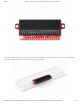
The breakout board lines up with the pins of a breadboard. We recommend using a full-sized breadboard with this breakout to
give you enough room to prototype circuits on either end of the breadboard. Also, for durability’s sake, insert the breakout pins
about halfway into the breadboard so there is support under the board for when you insert a micro:bit and/or pull it out.
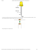
Introducing the LED
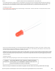
A Light-Emitting Diode (LED) will only let current through in one direction. Think of an LED as a one-way street. When current
flows through the LED, it lights up!
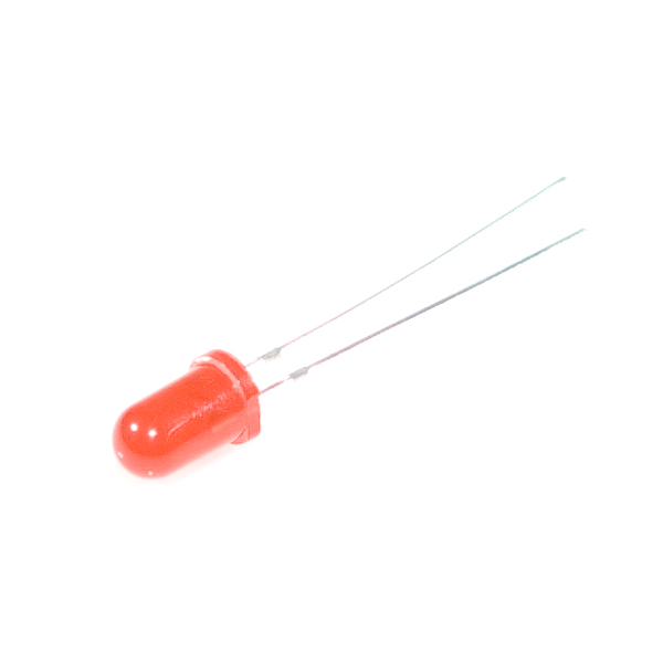
When you are looking at the LED, you will notice that its legs are different lengths. The long leg, the “anode,” is where current
enters the LED. This pin should always be connected to the current source. The shorter leg, the “cathode,” is the current’s exit.
The short leg should always be connected to a pathway to ground.
LEDs are finicky when it comes to how much current you apply to them. Too much current can lead to a burnt-out LED. To restrict
the amount of current that passes through the LED, we use a resistor in line with the power source and the LED’s long leg; this is
called a current-limiting resistor. With the micro:bit, you should use a 100Ω resistor. We have included a baggy of them in the kit
just for this reason!
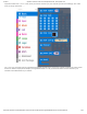
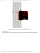
Hardware Hookup
Ready to start hooking everything up? Check out the wiring diagram and hookup table below to see how everything is connected.
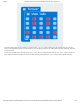
Polarized
Components
Pay special attention to the component’s markings indicating
how to place it on the breadboard. Polarized components can
only be connected to a circuit in one direction.
Please note: Pay close attention to the LED. The negative side of the LED is the short leg, marked with a flat edge.