
Guide

3/7/2018 SparkFun Inventor's Kit for micro:bit Experiment Guide - learn.sparkfun.com
https://learn.sparkfun.com/tutorials/sparkfun-inventors-kit-for-microbit-experiment-guide/all#introduction-to-microsoft-makecode 45/63
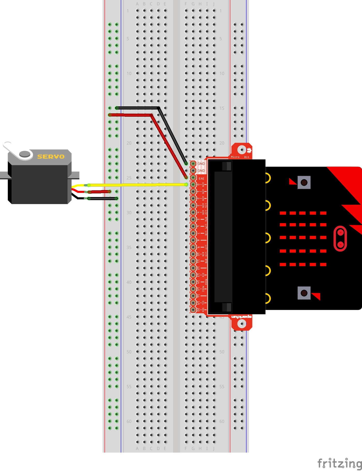
Hardware Hookup
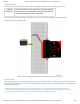
Ready to start hooking everything up? Check out the wiring diagram below to see how everything is connected.
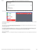
Polarized
Components
Pay special attention to the component’s markings indicating
how to place it on the breadboard. Polarized components can
only be connected to a circuit in one direction.
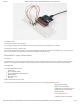
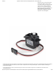
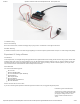
Connect 3x jumper wires to the female 3-pin header on the servo. This will make it easier to breadboard the servo.
Wiring Diagram for the Experiment
Having a hard time seeing the circuit? Click on the wiring diagram for a closer look.
Run Your Script
Either copy and paste, or re-create the following code into your own MakeCode editor by clicking the open icon in the upper right-
hand corner of the editor window. You can also just download this example by clicking the download button in the lower right-hand
corner of the code window.
Note: Controlling a servo with the micro:bit is not intended to give you a highly accurate angle of rotation, just basic
movement from one position to another to get your project movin'. If you are looking for a higher degree of accuracy from
your servo we recommend powering your servo motor with an external supply of 4.8V to 6V.