
Guide

3/7/2018 SparkFun Inventor's Kit for micro:bit Experiment Guide - learn.sparkfun.com
https://learn.sparkfun.com/tutorials/sparkfun-inventors-kit-for-microbit-experiment-guide/all#introduction-to-microsoft-makecode 32/63
Troubleshooting
Light Not Turning On
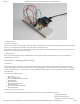
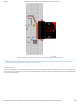
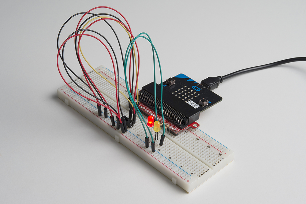
The wires for the switch are right next to each other. Make sure that signal is in the center with voltage and ground on the outside
pins. If you connect ground and voltage, your board will short out and shut down.
Make sure your power LED is on. If it is off, pull the signal wire and see if that changes anything. If you short circuit your micro:bit
board, it will turn itself off to protect the circuitry.
Underwhelmed
No worries; these circuits are all super stripped-down to make playing with the components easy, but once you throw them
together the sky is the limit.
Experiment 6: Reading a Button Press
Introduction
Up until now, we’ve focused mostly on outputs. Now we’re going to go to the other end of the spectrum and play around with
inputs. In Experiment 2, we used an analog input to read the potentiometer. In this experiment, we’ll be reading one of the most
common and simple inputs – a push button – by using a digital input. We will use it to cycle through different colors on the RGB.
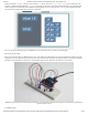
Parts Needed
You will need the following parts:
1x micro:bit
1x Micro B USB Cable
1x micro:bit Breakout (with Headers)
1x Breadboard
8x Jumper Wires
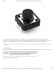
1x Momentary Push Button
1x 10kΩ Resistor
1x Common Cathode RGB LED
3x 100Ω Resistors
Didn’t Get the SIK for micro:bit?
If you are conducting this experiment and didn’t get the Inventor’s Kit, we suggest using these parts:
Suggested Reading
Before continuing with this
experiment, we recommend you be