
Guide

3/7/2018 SparkFun Inventor's Kit for micro:bit Experiment Guide - learn.sparkfun.com
https://learn.sparkfun.com/tutorials/sparkfun-inventors-kit-for-microbit-experiment-guide/all#introduction-to-microsoft-makecode 31/63
Note: You may need to disable your ad/pop-up blocker to interact with the MakeCode programming environment and
simulated circuit!
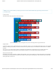
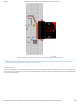
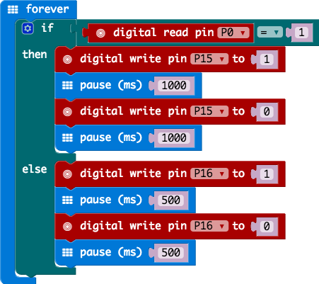
Code to Note
Let’s take a look at the code blocks in this experiment.
If you are having a hard time viewing this code, click on the image above to get a better look!
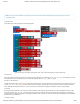
Digital Read
Just as the digital write block turns a pin on (1) or off (0) the digital read block looks at the state of a pin, which is either
HIGH (1) or LOW (0). By building a circuit that connects 3.3V or ground to a pin, we can detect if a switch is thrown or a button
pressed.
The digital read block returns a value so it is shaped to be inserted into a value slot and not a command. We use an
equivalency block from the logic blocks to check if the pin is equal to 1 or 0 and then make a decision from there.
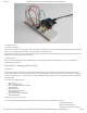
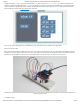
What You Should See
Depending on the state of the switch, a different LED will blink. If you move the switch to connect the signal pin to 3.3V (HIGH),
then the LED connected to pin P15 will blink. If you flip the switch and ground the signal pin, then the LED on pin P16 will start
blinking and LED 1 will turn off.