
Guide

3/7/2018 SparkFun Inventor's Kit for micro:bit Experiment Guide - learn.sparkfun.com
https://learn.sparkfun.com/tutorials/sparkfun-inventors-kit-for-microbit-experiment-guide/all#introduction-to-microsoft-makecode 29/63
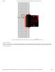
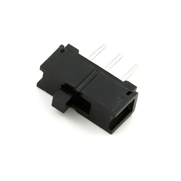
Reading a switch is similar to a button. You need to connect the common pin to a digital General Purpose Input/Output (GPIO) pin
to the micro:bit board from a breadboard. The other pins can be connected to 3.3V and ground. It doesn’t matter which pin is
which. When you move the switch, the common pin will either be HIGH (connected to 3.3V) or LOW (connected to ground).
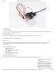
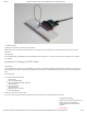
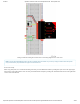
Hardware Hookup
Ready to start hooking everything up? Check out the wiring diagram and hookup table below to see how everything is connected.
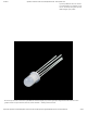
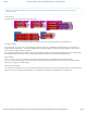
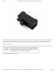
Polarized
Components
Pay special attention to the component’s markings indicating
how to place it on the breadboard. Polarized components can
only be connected to a circuit in one direction.
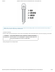
Wiring Diagram for the Experiment