
Guide

3/7/2018 SparkFun Inventor's Kit for micro:bit Experiment Guide - learn.sparkfun.com
https://learn.sparkfun.com/tutorials/sparkfun-inventors-kit-for-microbit-experiment-guide/all#introduction-to-microsoft-makecode 19/63
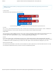
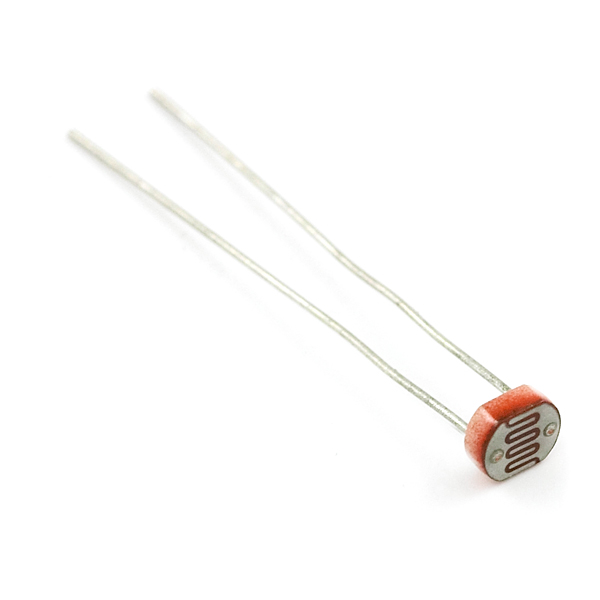
To use this with the micro:bit, you will need to build a voltage divider with a 10kΩ resistor, as shown in the wiring diagram for this
experiment. The micro:bit cannot read a change in resistance, only a change in voltage. A voltage divider allows you to translate a
change in resistance to a corresponding voltage value.
The voltage divider enables the use of resistance-based sensors like the photoresistor in a voltage-based system. As you explore
different sensors, you will find more resistance-based sensors that only have two pins like the photoresistor. To use them with your
micro:bit you will need to build a voltage divider like the one in this experiment. To learn more about resistors in general, check out
our tutorial on resistors and also our tutorial on voltage dividers.
Note: Make sure you are using the 10kΩ resistor in your voltage divider with the sensors in this kit. Otherwise you will get
odd and inconsistent results.
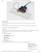
Hardware Hookup
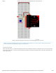
Ready to start hooking everything up? Check out the wiring diagram below to see how everything is connected.
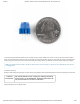
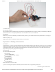
Polarized
Components
Pay special attention to the component’s markings indicating
how to place it on the breadboard. Polarized components can
only be connected to a circuit in one direction.
Wiring Diagram for the Experiment